1997ThunderbirdLXV6
Seasoned PostWhore
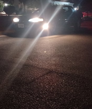
As you probably know by now, I love my cornering lights. My previous post on the subject is here:
And since I'd like to keep contributing content to our new community here, I figured I'd describe in more detail how these lights are wired. The great thing is, it's very easy!
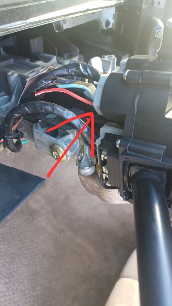
Ford multifunction switches from that period have the cornering light pins; however, the corresponding pins in the wiring connector are missing. This is the connector:

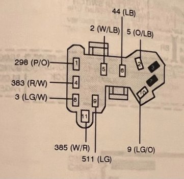
All you need to do is: go to a junkyard and pick up such a connector plus maybe 3" of wires. Using a tiny flathead (like the ones used for eyeglasses), open the connector (by removing the flat plastic retainer) and remove two of the wire terminals. Then open the connector in your car and push in the two wires until you hear a click. Place the plastic retainer back into the connector.
The two new wires go into positions 3 and 7. Sorry, I don't remember which is left and right.

Now all you have left to do is to extend the two wires and route them through the firewall. The cornering light feed is hot anytime the corresponding turn signal and the headlights are on.
Since this post is about wiring only, I won't go into detail regarding the light assemblies. I adapted units from an 80s Crown Vic, but there are countless options, e.g., hiding low-profile LED units below the bumper.
The most factory-ish installation is possible on pre-96 bumpers: those bumpers have outlines on the inside on each side, telling you exactly where to cut the bumper to install the OEM cornering lights. Those OEM units however are tough to find in junkyards.
Have fun!

And since I'd like to keep contributing content to our new community here, I figured I'd describe in more detail how these lights are wired. The great thing is, it's very easy!
Ford multifunction switches from that period have the cornering light pins; however, the corresponding pins in the wiring connector are missing. This is the connector:

All you need to do is: go to a junkyard and pick up such a connector plus maybe 3" of wires. Using a tiny flathead (like the ones used for eyeglasses), open the connector (by removing the flat plastic retainer) and remove two of the wire terminals. Then open the connector in your car and push in the two wires until you hear a click. Place the plastic retainer back into the connector.
The two new wires go into positions 3 and 7. Sorry, I don't remember which is left and right.

Now all you have left to do is to extend the two wires and route them through the firewall. The cornering light feed is hot anytime the corresponding turn signal and the headlights are on.
Since this post is about wiring only, I won't go into detail regarding the light assemblies. I adapted units from an 80s Crown Vic, but there are countless options, e.g., hiding low-profile LED units below the bumper.
The most factory-ish installation is possible on pre-96 bumpers: those bumpers have outlines on the inside on each side, telling you exactly where to cut the bumper to install the OEM cornering lights. Those OEM units however are tough to find in junkyards.
Have fun!

