As most of you know or have found out after trying to replace nonexistent bulbs, our interiors lack a lot of illumination that is normally found in modern cars.
The MN12 existed right between the era of having to flip on the map light to see what button you’re pressing and the current era of having to adjust the dimmer so the backlit “trunk release” button doesn’t blind you. From the bare bones functional sense you can confidentially use the radio, adjust the climate control, operate your windows/locks, and see all of your instruments with perfect clarity at night. Cruise, headlights and mirrors however, still have to require memory or glare to find. Hardly strenuous in the big picture since it's not difficult to familiarize yourself with the controls, but the rather incomplete looking lighting scheme sure is irritating from a pure aesthetic aspect at least.
WARNING: This is not for the faint of heart, you will have to live with a two things after this conversion:
1) You will not be able to use a single part from your existing steering wheel other than your airbag, even the hardware is different.
2) the illumination is limited to blue. The buttons are molded in translucent blue and painted black from the factory. *See update below
If these aren't a concern, read on...
Mark VIII's received cruise control illumination from the 1995 to 1998 model years. They use a special clockspring with 5 (rather than our 3) active terminals, the added two terminals being dedicated to illumination. The circuit itself has 1 small incandescent bulb per pod and 1 LED in the right side, otherwise the rest of the cruise circuit is identical to the MN12/SN95. The FN10 buttons themselves are translucent and allow for light to shine through whereas the MN12 and SN95 buttons are solid black plastic with the lettering printed on them.
You could theoretically swap the complete steering wheel and clockspring from a mark VIII directly into your MN12 and call it a day, however the steering wheels are wrapped differently and don't match the grain of our airbags particularly well. The Mustang wheel on the other hand is finished identically to ours despite having completely different hardware and electronics inside them (See illustration). For this how to I'll be covering the latter since this project revolved around my FR500 steering wheel.
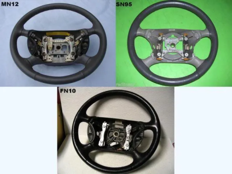
If anyone’s still wondering, the MN12 wheel and buttons unfortunately won’t interchange. The cruise mounting is different as well as minor proportions such as the switch plates, pivots and even the spacing between the spokes. It seems to be sheer luck that the Mustang switch plates and circuit boards interchange with the Mark VIII units. It appears that early on (93/94) they were 100% identical to the SN95 other than the bases. It’s a wonder why Ford didn’t equip the higher level Mustangs such as the Cobra with illuminated buttons considering the illumination note is even the same for the 94-00 models.
Tools needed:
-Phillips head screw driver
-Small flat blade screw driver (1/8 - 3/16 or so tip)
-Needle nose pliers
-Socket wrench with T50 Torx socket and 8mm socket
-Soldering iron and solder
-Shrink tubing and electrical tape
-An Electronic Vacuum Troubleshooting Manual would also be valuable to have.
Parts needed:
-1994-2004 Mustang Cruise equipped steering wheel and plastic shroud (the part between the column and airbag). If you too have been considering the FR500, now's a good time to grab one.
1994-2004 Mustang horn pads, wiring and hardware. I actually suggest sourcing these from a NON CRUISE equipped Mustang as they position the MN12 airbag much more flush with the wheel. The terminals also match the Mark VIII’s wiring harness terminal better(see below)
-1994-2004 Mustang cruise control buttons. Don't be too concerned about condition as you will only be using the mounting bases.
-1995-1998 Mark VIII cruise control buttons and wiring harness, don't worry if the mounting tabs are broken. (Note: Cruise buttons in these Marks were monochromatic so finding them in black can be difficult.)
-1995-1996[/b] Mark VIII clockspring assembly and the pigtail from the dash harness
Converting the buttons:
Note: I AM NOT RESPONSIBLE FOR ANY DAMAGE THAT CAN RESULT TO YOU OR YOUR CAR.
Note: If you’re using a complete Mark VIII steering wheel, skip steps 1 through 5.
1) Begin disassembling your SN95 and FN10 cruise buttons by gently prying on the buttons at the pivot points. On the right pod be sure to remove the set accell/coast buttons before resume.
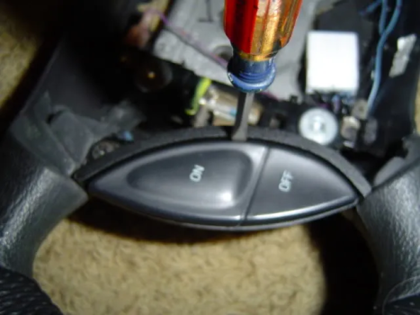
2) Carefully unclip the circuit boards from the bases and unplug the harness connector from the circuit. Mark the connectors and boards to help get the orientation right during reassembly. Discard the Marks bases and discard the Mustangs electronics and switch plates.
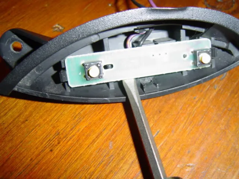
3) Run the Mark harness through the Mustang base and connect the circuit board. Before clipping it in you will need to clearance the base using the pliers to break off the alignment tabs and wire channel so the new circuits clear. Once everything’s out of the way clip them in.
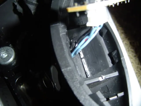
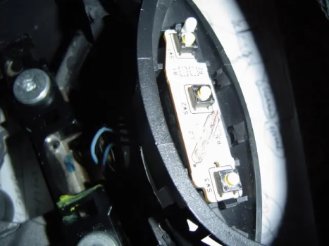
Note: Some Mustang bases have a smaller opening for the harness to go through, if that's the case enlarge it with a 1/4" drill.
4) Place the rubber inserts over the boards and carefully clip on the switches from the outside in.
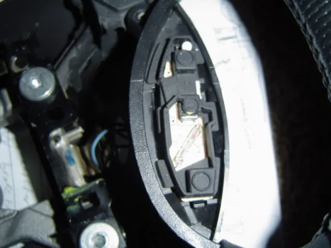
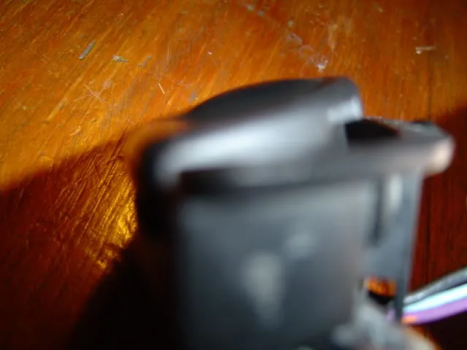
5) Mount the buttons and horn pads to the steering wheel
Now what needs to happen here is a bit unique. The Mark VIII harness will have only 2 spade connectors for the horn buttons, power(p/o wire) and ground(bk).
The ground wire can be eliminated completely since the SN95 buttons ground through the chassis, but The power will need an additional wire so both sides of the horn pads can activate the horn.
Obvious solution is to splice an extra spade connector into the harness. The other solution though is virtually plug and play. Use the Mustang non-cruise horn harness between the top two horn pad terminals and attach the single Mark spade connector to the bottom terminals of one of the horn pads. The harness acts as a jumper tosupply power to both pads. Just tuck the Mustang harness's clockspring connector out of the way(the shroud has a convenient mount tab for it) and you're good to go
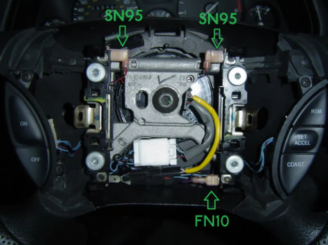
Here we see the wheel assembled in the car, the arrows show which harness is connected to which terminal.
Note the unused connector under the top left SN95 arrow, this is the connector for the old clockspring to power the Mustang horn pads. It is left unused and out of the way since the power is being supplied by the lone Mark VIII spade connector.
Set the assembled wheel aside for now as we move onto the chassis.
Converting the car
6) Unhook the battery and let it sit for a few minutes.
7) Remove the round access covers on the steering shroud, unbolt the airbag and unclip the connectors. Remove the steering wheel after loosening the torx bolt retaining it. Also remove the column shroud, knee panel, and floor vent duct underneath the column.
8) Remove and replace the factory clockspring with the Mark VIII one.
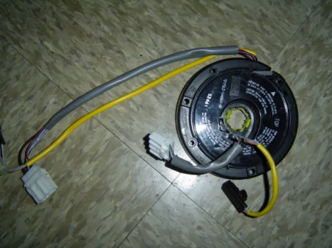
9)a Cut the stock pigtail off the dash harness and splice the Mark one in it’s place, just match the circuits pertaining to cruise and horn for now.
9)b an alternative to cutting the dash pigtail is cutting and splicing your MN12 clockspring connector onto the FN10 clockspring. This would leave the dash wiring relatively untouched besides the need to splice the illumination wires of course. Only downside is the illumination wires would tie the clockspring perminantly to the dash once spliced though(unless you added an inline connector. But if you're going to the trouble of that it's not any easier than 9a really)
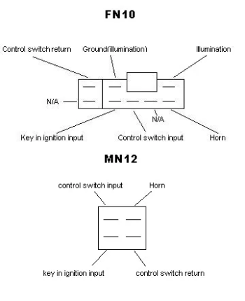
Note: viewed from open dash connector
10) For the remaining two wires you’ll need to tap into an illumination circuit in the dash, the illumination wires are usually LB/R. You can simply run the ground to the chassis or splice into another known ground An EVTM is very handy to have for this step, particularly for the power distribution sections. I actually tapped into an unused terminal in the secondary junction box for my illumination feed so as to make a very factory like setup, which without an EVTM can be very difficult to do without probing every terminal on the SJB with a meter.
11) Shrink wrap and Tape up all of the exposed wires, connect the new pigtail to the clockspring as well as the 2 pin airbag connector and reassemble all of the parts removed in step 7.
12) Install the steering wheel, connect the white cruise connector to the clockspring, connect the airbag to the clockspring, reinstall the airbag.
Note: one way to make the install even cleaner is to drill a 1/4" hole into the shroud to clip the Mark VIII harness connector into. The photo illustrating the horn pad wiring above shows where and how I mounted it
13) Connect the battery, turn on the headlights and go for a nice cruise at dusk to admire your work that nobody else but you notices
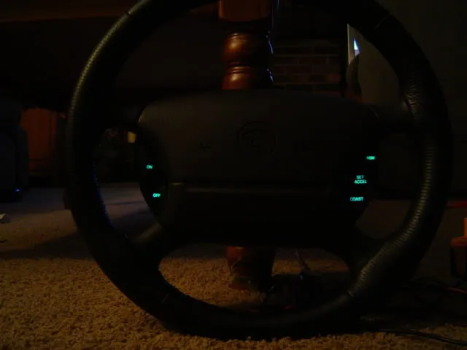
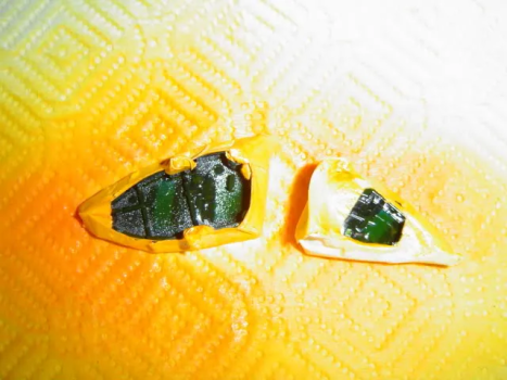
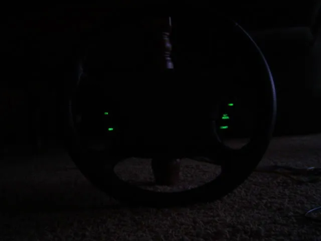
Update: It is possible to change the illumination from blue to green by using yellow translucent paint on the backs of the switches like so...
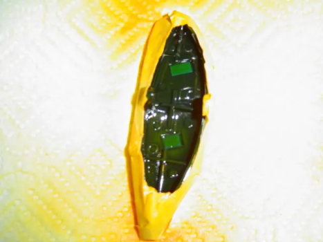
Thanks to theterminator93 for this suggestion!
-Matt
The MN12 existed right between the era of having to flip on the map light to see what button you’re pressing and the current era of having to adjust the dimmer so the backlit “trunk release” button doesn’t blind you. From the bare bones functional sense you can confidentially use the radio, adjust the climate control, operate your windows/locks, and see all of your instruments with perfect clarity at night. Cruise, headlights and mirrors however, still have to require memory or glare to find. Hardly strenuous in the big picture since it's not difficult to familiarize yourself with the controls, but the rather incomplete looking lighting scheme sure is irritating from a pure aesthetic aspect at least.
WARNING: This is not for the faint of heart, you will have to live with a two things after this conversion:
1) You will not be able to use a single part from your existing steering wheel other than your airbag, even the hardware is different.
2) the illumination is limited to blue. The buttons are molded in translucent blue and painted black from the factory. *See update below
If these aren't a concern, read on...
Mark VIII's received cruise control illumination from the 1995 to 1998 model years. They use a special clockspring with 5 (rather than our 3) active terminals, the added two terminals being dedicated to illumination. The circuit itself has 1 small incandescent bulb per pod and 1 LED in the right side, otherwise the rest of the cruise circuit is identical to the MN12/SN95. The FN10 buttons themselves are translucent and allow for light to shine through whereas the MN12 and SN95 buttons are solid black plastic with the lettering printed on them.
You could theoretically swap the complete steering wheel and clockspring from a mark VIII directly into your MN12 and call it a day, however the steering wheels are wrapped differently and don't match the grain of our airbags particularly well. The Mustang wheel on the other hand is finished identically to ours despite having completely different hardware and electronics inside them (See illustration). For this how to I'll be covering the latter since this project revolved around my FR500 steering wheel.

If anyone’s still wondering, the MN12 wheel and buttons unfortunately won’t interchange. The cruise mounting is different as well as minor proportions such as the switch plates, pivots and even the spacing between the spokes. It seems to be sheer luck that the Mustang switch plates and circuit boards interchange with the Mark VIII units. It appears that early on (93/94) they were 100% identical to the SN95 other than the bases. It’s a wonder why Ford didn’t equip the higher level Mustangs such as the Cobra with illuminated buttons considering the illumination note is even the same for the 94-00 models.
Tools needed:
-Phillips head screw driver
-Small flat blade screw driver (1/8 - 3/16 or so tip)
-Needle nose pliers
-Socket wrench with T50 Torx socket and 8mm socket
-Soldering iron and solder
-Shrink tubing and electrical tape
-An Electronic Vacuum Troubleshooting Manual would also be valuable to have.
Parts needed:
-1994-2004 Mustang Cruise equipped steering wheel and plastic shroud (the part between the column and airbag). If you too have been considering the FR500, now's a good time to grab one.
1994-2004 Mustang horn pads, wiring and hardware. I actually suggest sourcing these from a NON CRUISE equipped Mustang as they position the MN12 airbag much more flush with the wheel. The terminals also match the Mark VIII’s wiring harness terminal better(see below)
-1994-2004 Mustang cruise control buttons. Don't be too concerned about condition as you will only be using the mounting bases.
-1995-1998 Mark VIII cruise control buttons and wiring harness, don't worry if the mounting tabs are broken. (Note: Cruise buttons in these Marks were monochromatic so finding them in black can be difficult.)
-1995-1996[/b] Mark VIII clockspring assembly and the pigtail from the dash harness
Converting the buttons:
Note: I AM NOT RESPONSIBLE FOR ANY DAMAGE THAT CAN RESULT TO YOU OR YOUR CAR.
Note: If you’re using a complete Mark VIII steering wheel, skip steps 1 through 5.
1) Begin disassembling your SN95 and FN10 cruise buttons by gently prying on the buttons at the pivot points. On the right pod be sure to remove the set accell/coast buttons before resume.

2) Carefully unclip the circuit boards from the bases and unplug the harness connector from the circuit. Mark the connectors and boards to help get the orientation right during reassembly. Discard the Marks bases and discard the Mustangs electronics and switch plates.

3) Run the Mark harness through the Mustang base and connect the circuit board. Before clipping it in you will need to clearance the base using the pliers to break off the alignment tabs and wire channel so the new circuits clear. Once everything’s out of the way clip them in.


Note: Some Mustang bases have a smaller opening for the harness to go through, if that's the case enlarge it with a 1/4" drill.
4) Place the rubber inserts over the boards and carefully clip on the switches from the outside in.


5) Mount the buttons and horn pads to the steering wheel
Now what needs to happen here is a bit unique. The Mark VIII harness will have only 2 spade connectors for the horn buttons, power(p/o wire) and ground(bk).
The ground wire can be eliminated completely since the SN95 buttons ground through the chassis, but The power will need an additional wire so both sides of the horn pads can activate the horn.
Obvious solution is to splice an extra spade connector into the harness. The other solution though is virtually plug and play. Use the Mustang non-cruise horn harness between the top two horn pad terminals and attach the single Mark spade connector to the bottom terminals of one of the horn pads. The harness acts as a jumper tosupply power to both pads. Just tuck the Mustang harness's clockspring connector out of the way(the shroud has a convenient mount tab for it) and you're good to go

Here we see the wheel assembled in the car, the arrows show which harness is connected to which terminal.
Note the unused connector under the top left SN95 arrow, this is the connector for the old clockspring to power the Mustang horn pads. It is left unused and out of the way since the power is being supplied by the lone Mark VIII spade connector.
Set the assembled wheel aside for now as we move onto the chassis.
Converting the car
6) Unhook the battery and let it sit for a few minutes.
7) Remove the round access covers on the steering shroud, unbolt the airbag and unclip the connectors. Remove the steering wheel after loosening the torx bolt retaining it. Also remove the column shroud, knee panel, and floor vent duct underneath the column.
8) Remove and replace the factory clockspring with the Mark VIII one.

9)a Cut the stock pigtail off the dash harness and splice the Mark one in it’s place, just match the circuits pertaining to cruise and horn for now.
9)b an alternative to cutting the dash pigtail is cutting and splicing your MN12 clockspring connector onto the FN10 clockspring. This would leave the dash wiring relatively untouched besides the need to splice the illumination wires of course. Only downside is the illumination wires would tie the clockspring perminantly to the dash once spliced though(unless you added an inline connector. But if you're going to the trouble of that it's not any easier than 9a really)

Note: viewed from open dash connector
10) For the remaining two wires you’ll need to tap into an illumination circuit in the dash, the illumination wires are usually LB/R. You can simply run the ground to the chassis or splice into another known ground An EVTM is very handy to have for this step, particularly for the power distribution sections. I actually tapped into an unused terminal in the secondary junction box for my illumination feed so as to make a very factory like setup, which without an EVTM can be very difficult to do without probing every terminal on the SJB with a meter.
11) Shrink wrap and Tape up all of the exposed wires, connect the new pigtail to the clockspring as well as the 2 pin airbag connector and reassemble all of the parts removed in step 7.
12) Install the steering wheel, connect the white cruise connector to the clockspring, connect the airbag to the clockspring, reinstall the airbag.
Note: one way to make the install even cleaner is to drill a 1/4" hole into the shroud to clip the Mark VIII harness connector into. The photo illustrating the horn pad wiring above shows where and how I mounted it
13) Connect the battery, turn on the headlights and go for a nice cruise at dusk to admire your work that nobody else but you notices


Update: It is possible to change the illumination from blue to green by using yellow translucent paint on the backs of the switches like so...


Thanks to theterminator93 for this suggestion!
-Matt
Last edited:
