- Joined
- Sep 12, 2023
- Messages
- 2,527
- Location
- North Ridgeville, OH
- Cars in Garage
- 2
- Vehicle Details
- 1997 Thunderbird 4.6, 1998 Mark VIII LSC
All Mark VIIIs received illuminated headlight trim from the factory whereas no MN12s did. The first generation (93-96) Mark VIII switch trimpieces had "cutout" areas in the trim around the switch where translucent stenciled plastic was installed and backlit, along with a small portion of the headlight switch knob itself. Identically to the MN12 setup, the headlight switch controlled parking lamps and headlamps, and there were separate knobs for autolamp delay and interior illumination and courtesy lamps. The 2nd generation Mark VIIIs received a more refined design with a single molded translucent plastic trimpiece which had an opaque coating on the front with stenciled letters which were backlit. The headlight switch and autolamp dimmer were integrated into one switch, eliminating the separate autolamp dial. The rotation of the courtesy lamps/interior illumination dimmer dial was also reversed. These 2nd generation trimpieces, when centered directly behind the hole in the MN12 gauge cluster trim, provide a stock-like appearance similar to the rest of the interior.
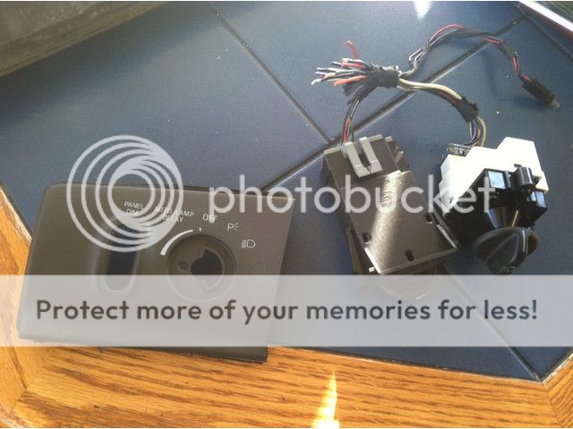
In addition, the 2nd gen FN10 dash came in multiple colors. This works to the advantage of Cougar owners who wish to color match their headlight switch trim to the color of their instrument cluster trim. For Thunderbird owners, black is the only color which will match the instrument cluster trim. You can find black headlight trimpieces from 1997 Mark VIIIs; in 1998 the black color was altered slightly to a slightly lighter charcoal gray. This color variance can be seen below as the switch hardware I acquired was from a 1998 model FN10.
The goal is to install the 2nd generation Mark VIII headlight and autolamp trimpiece and switches in place of the MN12 trimpiece, headlight and dimmer switch. There are several issues with the installation of these components, both physically and electrically. These are as follows:
PREPARING THE SWITCH
In order to make the switch compatible with the MN12 electrical systems, we need to modify it so that when it is in an autolamp position there is a path to ground with variable increasing resistance. The autolamp amplifier also needs a direct path to ground to turn the headlights on. We will also need to bypass several resistors so that relays can engage when those circuits are closed so that the manual lights positions operate.
Step 1: Use a small screwdriver to gently pry open the FN10 headlight switch to gain access to the circuit board. Then pry the circuit board out of the switch housing.
Step 2: Following the diagrams below, use an exacto knife to cut several traces, remove and bypass three resistors and solder in bypass wiring using 22-26 AWG wire.


You should have something that looks similar to this when you are done. For the wire that connects the center-left contact patch face to pin 6 for the autolamps on trigger, I suggest running the wire through the hole at the center of the switch to the back so it does not interfere with the rotating contacts on the switch knob. Note that I did not yet bypass the resistors in this photo! Make sure you bypass the three large resistors otherwise the switch will not work in any position!


Step 3: Reassemble the switch. You may want to remove the several unused wires coming from the switch harness that do not connect with any terminals on the switch to minimize clutter and confusion later. The only wires necessary are the 6 terminals on the switch.
Step 4: To achieve a match to the factory green color in the car, gently cut away at the blue "posts" holding the tan light shield in place from the back of the switch trim and remove the light spreader. Paint this area with the translucent yellow paint. Reinstall the light spreader and light shield with plastic epoxy. Let this cure for at least several hours before handling.

PREPARING THE CAR:
Step 1: Disconnect the negative battery cable. Remove the three bolts at the bottom of the steering column cover holding it in place (either 10mm or 8mm depending on model year) and remove the cover. There are three speed nuts at the top, so be careful removing it so as not to break them off. Then remove the five 7mm bolts holding the gauge cluster trim in piece. Lower the steering wheel to its lowest tilt setting. Be careful breaking it loose it as there is a speed nut at the back between the left air vent and left side of the hole for the instrument cluster as well as several clips on the far right. Once you have clearance from behind, unclip the defrost switch harness, then remove the trimpiece. Be extremely careful to not flex the trimpiece too greatly. The ABS plastic is very brittle with its age and breaks easily.
Step 2: Pull off the knob from the headlight switch then use a 19mm socket to remove the nut holding the trimpiece to the headlight switch. Remove the trimpiece then squeeze the clips on the top and bottom of the courtesy lamp/autolamp dials and pull it towards you to remove the harness and the switch. Unbolt the headlight switch, pull it out and remove the harness and switch.
Step 3: Cut the wires leading to the MN12 headlight switch plug and the two wires from the autolamp harness plug and splice them together with the FN10 headlight switch harness as diagrammed below. There are quite a few ground connections here; it may be best to run a new ground bus for all the new grounds rather than try to splice into the same grounds multiple times. Note: The two grounds that terminate at the headlight switch must be connected together. Also be CERTAIN that all splices are completely wrapped with shrink tubing or electrical tape to prevent shorts and electrical fires! If you don't already have a relay harness on the headlights circuit, be CERTAIN you connect the yellow and red/yellow wires DIRECTLY to the relay or that the wire spliced to it which connects to the relay is at least 14 AWG to handle 15 amps.

Step 4: Install female spade terminals and connect the three relays to the FN10 headlight switch and MN12 headlight switch wiring harness as diagrammed above. One relay handles the current for the headlights, another handles current for the parking lamps. A third relay completes a ground circuit whenever parking lamps or headlamps are on manually to turn on the "ignition off, headlights on" warning chime. Dress up the wiring after you've finished splicing everything to keep it all neat and organized before stuffing it all down into the steering column cavity. I also suggest cable tying the relays to something solid to keep them from rattling against other objects from the vibrations of the car. Note: I have not included the wiring of the illumination for the switch trim in the diagram. Splice into the red/blue wire from the courtesy lamps dimmer switch harness and ground to power the light for the trim.
Step 5: There is no concrete way to do this, unfortunately. This will requite a lot of trial and error on your part. Use a Dremel or similar rotary cutting tool to remove the plastic support webbing that the stock switches attached to. You will also need to cut off most of the border of the FN10 switch trim so it fits behind the instrument cluster trim. The goal here is to epoxy the FN10 switch mounting plate in place of the MN12 switch mount. You will need to experiment somewhat with the fitment by temporarily installing the switch into the backing plate and clipping the trim to the backing plate, making additional cuts, measuring, etc. etc. It took me a good 45 minutes of cutting to get the results I wanted. Once you have cut enough material from the dash so the FN10 switch mount fits with the trimpiece snug against and centered with the back of the instrument cluster trim, use a hot glue gun to secure it in place temporarily so you can use a plastic epoxy to permanently fix it in place.

Step 6: Once the epoxy has cured overnight, you should be able to install the switch and MN12 non-autolamp courtesy lamps dimmer switch into the FN10 mount. Hook the battery cable up again and test the courtesy lamps and manual headlight positions with the ignition off. Then with the ignition on, test the autolamps. Once you're satisfied that everything works, install the FN10 trimpiece and reinstall the instrument cluster and steering column trimpieces, then stare at your new lights with satisfaction.


In addition, the 2nd gen FN10 dash came in multiple colors. This works to the advantage of Cougar owners who wish to color match their headlight switch trim to the color of their instrument cluster trim. For Thunderbird owners, black is the only color which will match the instrument cluster trim. You can find black headlight trimpieces from 1997 Mark VIIIs; in 1998 the black color was altered slightly to a slightly lighter charcoal gray. This color variance can be seen below as the switch hardware I acquired was from a 1998 model FN10.
The goal is to install the 2nd generation Mark VIII headlight and autolamp trimpiece and switches in place of the MN12 trimpiece, headlight and dimmer switch. There are several issues with the installation of these components, both physically and electrically. These are as follows:
- The MN12 has separate switches for headlights and autolamps. The 2nd gen FN10 has a single switch which integrates the functions of the separate MN12 autolamp and headlight switches.
- The FN10 and MN12 headlight switches mount differently and have different form factors.
- The FN10 trimpiece requires that the positions of the headlight switch and courtesy lamps/instruments illumination dimmer be reversed from their MN12 arrangement.
- The MN12 headlight switch handles all the current for the parking lamps and headlamps. The FN10 headlight switch does not direct any current to the headlights or parking lamps directly, but switches them on via a lighting control module. As such it is incapable of handling the large amounts of electrical current which those circuits require.
- The FN10 headlight switch trim does not light up green like the MN12 interior, but rather it lights up a blue color.
- The electrical requirements of the MN12 autolamp system is not compatible with the FN10 switch's integrated dimming.
- The FN10 courtesy lamps/instrument illumination dimmer switch functionality is not compatible with the electrical requirements of the MN12 lighting system.
- The FN10 headlight switch does not include provisions to operate the "headlights on, ignition off" warning chime.
- 1997-98 Mark VIII headlight/autolamp switch and harness pigtail, with approx. ~6" of wire
- 1997-98 Mark VIII headlight/autolamp switch trimpiece
- 1997-98 Mark VIII headlight switch trimpiece backing plate (this is molded as part of the instrument cluster surround; you will need to cut it off)
- 1994-97 MN12 non-autolamp dimmer switch
- Three automotive grade relays (I used 30A SPST relays from Radio Shack)
- 12 female slide connector terminals
- Solder, soldering iron (a butane torch may be necessary for larger gauge wire splices)
- Electrical tape or heat shrink tubing and a hair drier or heat gun
- Hot glue/hot glue gun
- Plastic epoxy
- Utility knife/plastic modeling knife
- Several feet of 14-16 AWG wire
- Several inches of 22-26 AWG wire
- Translucent yellow paint (I used Createx Airbrush Colors Brite Yellow)
PREPARING THE SWITCH
In order to make the switch compatible with the MN12 electrical systems, we need to modify it so that when it is in an autolamp position there is a path to ground with variable increasing resistance. The autolamp amplifier also needs a direct path to ground to turn the headlights on. We will also need to bypass several resistors so that relays can engage when those circuits are closed so that the manual lights positions operate.
Step 1: Use a small screwdriver to gently pry open the FN10 headlight switch to gain access to the circuit board. Then pry the circuit board out of the switch housing.
Step 2: Following the diagrams below, use an exacto knife to cut several traces, remove and bypass three resistors and solder in bypass wiring using 22-26 AWG wire.
You should have something that looks similar to this when you are done. For the wire that connects the center-left contact patch face to pin 6 for the autolamps on trigger, I suggest running the wire through the hole at the center of the switch to the back so it does not interfere with the rotating contacts on the switch knob. Note that I did not yet bypass the resistors in this photo! Make sure you bypass the three large resistors otherwise the switch will not work in any position!
Step 3: Reassemble the switch. You may want to remove the several unused wires coming from the switch harness that do not connect with any terminals on the switch to minimize clutter and confusion later. The only wires necessary are the 6 terminals on the switch.
Step 4: To achieve a match to the factory green color in the car, gently cut away at the blue "posts" holding the tan light shield in place from the back of the switch trim and remove the light spreader. Paint this area with the translucent yellow paint. Reinstall the light spreader and light shield with plastic epoxy. Let this cure for at least several hours before handling.
PREPARING THE CAR:
Step 1: Disconnect the negative battery cable. Remove the three bolts at the bottom of the steering column cover holding it in place (either 10mm or 8mm depending on model year) and remove the cover. There are three speed nuts at the top, so be careful removing it so as not to break them off. Then remove the five 7mm bolts holding the gauge cluster trim in piece. Lower the steering wheel to its lowest tilt setting. Be careful breaking it loose it as there is a speed nut at the back between the left air vent and left side of the hole for the instrument cluster as well as several clips on the far right. Once you have clearance from behind, unclip the defrost switch harness, then remove the trimpiece. Be extremely careful to not flex the trimpiece too greatly. The ABS plastic is very brittle with its age and breaks easily.
Step 2: Pull off the knob from the headlight switch then use a 19mm socket to remove the nut holding the trimpiece to the headlight switch. Remove the trimpiece then squeeze the clips on the top and bottom of the courtesy lamp/autolamp dials and pull it towards you to remove the harness and the switch. Unbolt the headlight switch, pull it out and remove the harness and switch.
Step 3: Cut the wires leading to the MN12 headlight switch plug and the two wires from the autolamp harness plug and splice them together with the FN10 headlight switch harness as diagrammed below. There are quite a few ground connections here; it may be best to run a new ground bus for all the new grounds rather than try to splice into the same grounds multiple times. Note: The two grounds that terminate at the headlight switch must be connected together. Also be CERTAIN that all splices are completely wrapped with shrink tubing or electrical tape to prevent shorts and electrical fires! If you don't already have a relay harness on the headlights circuit, be CERTAIN you connect the yellow and red/yellow wires DIRECTLY to the relay or that the wire spliced to it which connects to the relay is at least 14 AWG to handle 15 amps.
Step 4: Install female spade terminals and connect the three relays to the FN10 headlight switch and MN12 headlight switch wiring harness as diagrammed above. One relay handles the current for the headlights, another handles current for the parking lamps. A third relay completes a ground circuit whenever parking lamps or headlamps are on manually to turn on the "ignition off, headlights on" warning chime. Dress up the wiring after you've finished splicing everything to keep it all neat and organized before stuffing it all down into the steering column cavity. I also suggest cable tying the relays to something solid to keep them from rattling against other objects from the vibrations of the car. Note: I have not included the wiring of the illumination for the switch trim in the diagram. Splice into the red/blue wire from the courtesy lamps dimmer switch harness and ground to power the light for the trim.
Step 5: There is no concrete way to do this, unfortunately. This will requite a lot of trial and error on your part. Use a Dremel or similar rotary cutting tool to remove the plastic support webbing that the stock switches attached to. You will also need to cut off most of the border of the FN10 switch trim so it fits behind the instrument cluster trim. The goal here is to epoxy the FN10 switch mounting plate in place of the MN12 switch mount. You will need to experiment somewhat with the fitment by temporarily installing the switch into the backing plate and clipping the trim to the backing plate, making additional cuts, measuring, etc. etc. It took me a good 45 minutes of cutting to get the results I wanted. Once you have cut enough material from the dash so the FN10 switch mount fits with the trimpiece snug against and centered with the back of the instrument cluster trim, use a hot glue gun to secure it in place temporarily so you can use a plastic epoxy to permanently fix it in place.
Step 6: Once the epoxy has cured overnight, you should be able to install the switch and MN12 non-autolamp courtesy lamps dimmer switch into the FN10 mount. Hook the battery cable up again and test the courtesy lamps and manual headlight positions with the ignition off. Then with the ignition on, test the autolamps. Once you're satisfied that everything works, install the FN10 trimpiece and reinstall the instrument cluster and steering column trimpieces, then stare at your new lights with satisfaction.