- Joined
- Sep 12, 2023
- Messages
- 2,037
- Location
- North Ridgeville, OH
- Cars in Garage
- 2
- Vehicle Details
- 1997 Thunderbird 4.6, 1998 Mark VIII LSC
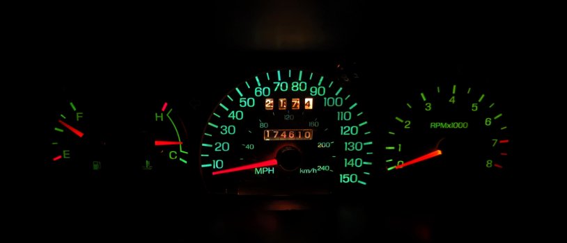
The 89-96 MN12 guys get to upgrade their 120 MPH speedometers with the 145 MPH speedometer found in the Super Coupe, but those of us with a 97 can do a little better. The 96-99 Taurus came with a gauge cluster very similar to that found in the 1997 MN12. The SHO has a speedometer that goes up to 150 MPH and also has an 8000 RPM tachometer. It is possible to drop-in the 150 MPH speedometer with no other modifications, though the illumination for the Taurus is blue. You can paint the back of the gauge face with a translucent yellow paint to get a very close match to the MN12 green.
It is also possible to upgrade to the 8000 RPM tachometer. Trying to install the SHO cluster won't work directly because the circuit pinouts are almost all different. I determined that it is more reasonable to repin/rewire the stock cluster for the SHO gauges than to repin the SHO cluster for the MN12. The list of wires to move was 20+ items long, and I'm not 100% sure that some of the circuits use the same signal inputs. Putting the SHO gauges into the MN12 cluster does work, however; in order to ensure the correct indicator lights up, it is necessary to either rewire the cluster for the new warning light positions, or use custom gauge faces.
I previously tried using custom gauge faces, but was unsatisfied with the quality of them and opted to retrofit the gauges with the original SHO faces. The 96-97 SHO gauges are black like the MN12's; the 98-99 faces are white.
Here's the plan of attack. I numbered pins from 1-32 from L to R while looking at the back of the cluster:
Remove pin #3 white/light green O/D off
Remove pin #4 black/light blue T/A off
Remove pin #20 dark green/light green Seat Belt
Remove pin #28 pink/white Brake
Remove pin #29 white/red Oil
Cut trace to LO WASH bulb; run wire from module to seat belt bulb trace
Cut trace to LO COOLANT bulb; run wire from module to BRAKE bulb trace
Install pin #29 white/red wire to slot #3
Install pin #28 pink/white wire to slot #4
Install pin #20 dark green/light green wire to slot #29
Install pin #3 white/light green to socket #9 not used; add wire to unused bulb socket trace; cut plastic & install bulb
Install pin #4 to slot #28; cut trace before LOW WASH wire & install wire (before cut/harness wire of trace) to LO WASH bulb
That gets all the idiot lights lined up, save for T/A off lighting up as REAR LAMP OUT. If you're like me and have traction assist, you rarely pay attention to it so it isn't much of a concern.
HARNESS PREP
Remove plastic sheathing around both connector harnesses, and unwrap the electrical tape bundling them together
Remove pin #3 white/light green (O/D off)
Remove pin #4 black/light blue (T/A off)
Remove pin #20 dark green/light green (Seat Belt)
Remove pin #28 purple/white (Brake)
Remove pin #29 white/red (Oil)
Pins 28 and 29 need to be moved to the white connector side, and pin 4 gets moved to the black connector side
LOW COOLANT
Cut trace from LOW FLUIDS MODULE to LO COOLANT bulb
Cut trace #28 BRAKE between bulb socket and pigtail socket
Run wire from LOW FLUIDS MODULE trace #4 to bulb side of trace #28
LOW WASHER
Cut trace from LOW FLUIDS MODULE to LO WASH bulb
Cut trace between LTS bulb and S BELT bulb
Run wire from LOW FLUIDS MODULE trace #5 to lower/right trace of S BELT bulb
Run wire from +12V key on trace #27 to cluster trace #20 S BELT bulb
ABS (Option)
Run wire from ABS bulb/cluster trace #26 to LO COOLANT bulb side of trace
O/D OFF
Run jumper wire from +12V key on trace #6 to top/left contact of unused bulb socket
Cut GROUND trace around bottom/right contact of unused bulb socket to isolate contact
Run jumper wire around newly isolated contact from GROUND circuit near ILL lamp to GROUND circuit near LOW FLUIDS MODULE
Run wire from unused cluster trace #9 to bottom/right contact of unused bulb socket, install pin #3 white/light green in position #9 of pigtail
Cut hole in circuit plastic using cluster hole as a guide; scrape away plastic over contacts to provide electrical contact for bulb
Install spare bulb into socket
T/A OFF (option)
Run wire from LO WASH bulb trace to vehicle harness side of cluster pin #28
Install pin #4 black/light blue into position #28 of pigtail
* The 8k tach face in this position reads "REAR LAMP OUT", which was not used in the SHO cluster. Preferring a seamless, clean look, I chose to wire my T/A off light here. *
SEAT BELT
Install pin #20 dark green/light green into position #29 of pigtail
Cut trace #27 immediately before "OIL" text and before the "Y" splitting the trace to anti-slosh module and SES/Ajar lights - making sure to leave continuity between the SES/Ajar lights and the anti-slosh module (see picture)
Install bypass wire from trace #27 near fuel gauge "I" text to trace #27 to trace feeding anti-slosh module and SES/Ajar lights
Add wire from newly isolated trace on bottom side of OIL PRESS bulb to ground (trace with PRESS)
OIL PRESSURE
Install pin #29 white/red into position #3 of pigtail
BRAKE
Install pin #28 pink/white into position #4 of pigtail
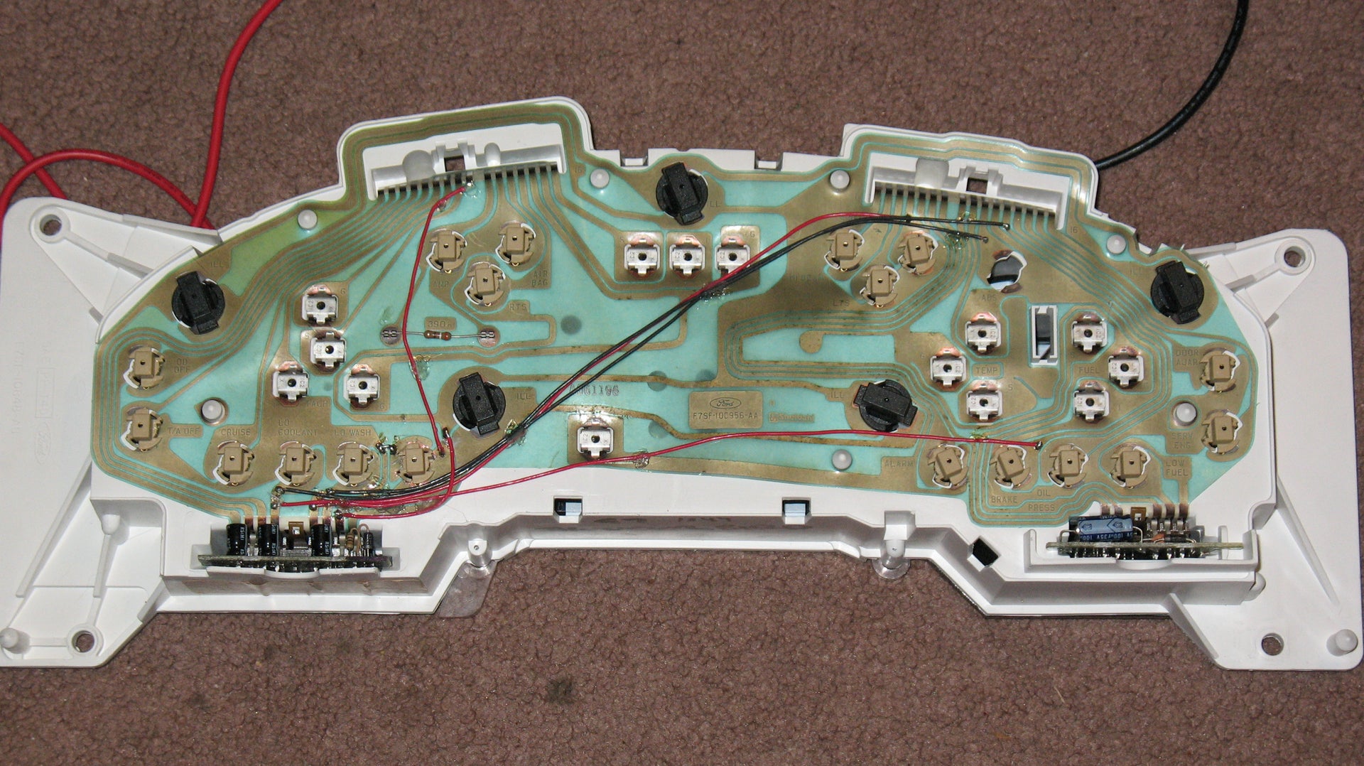
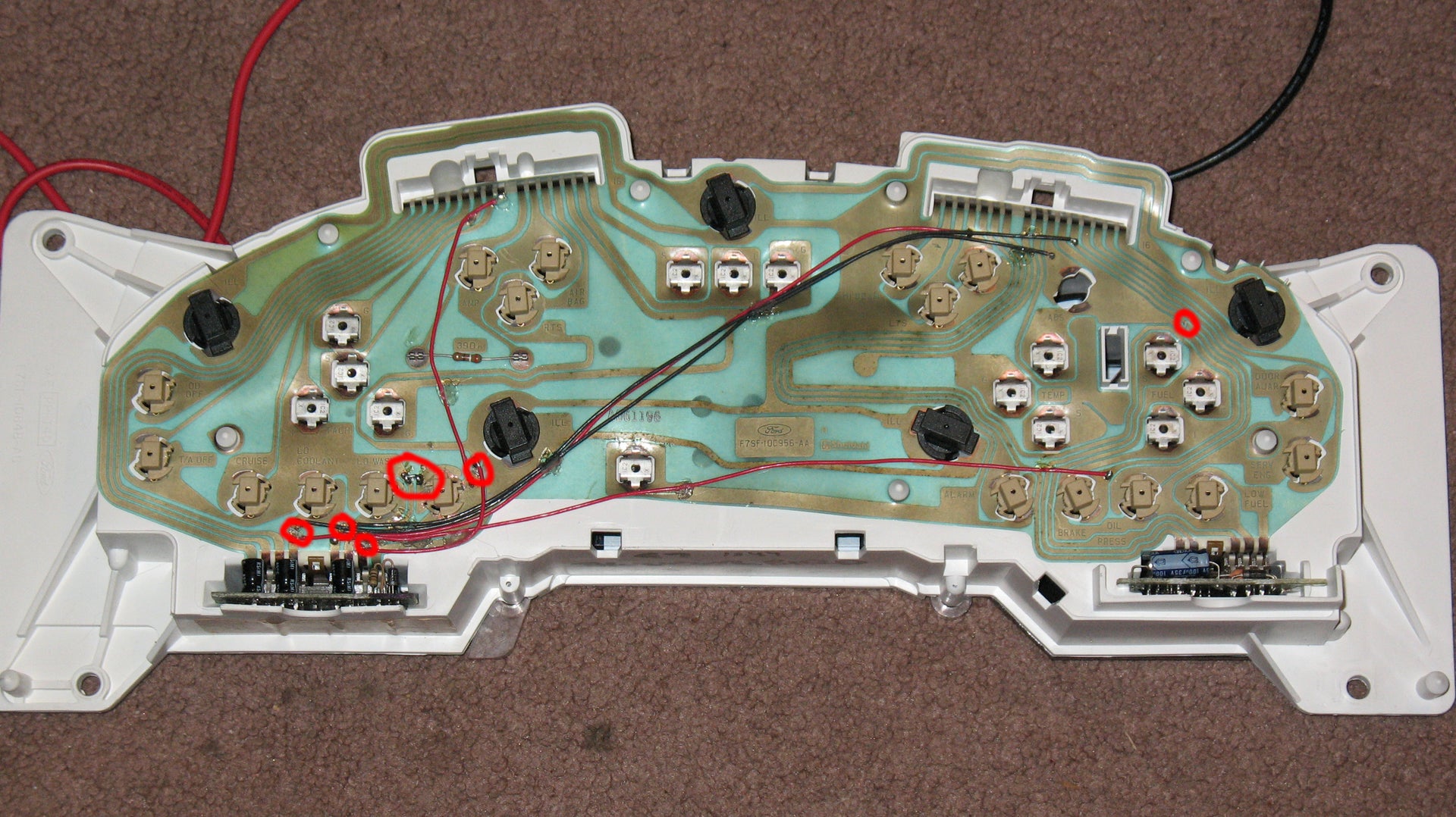
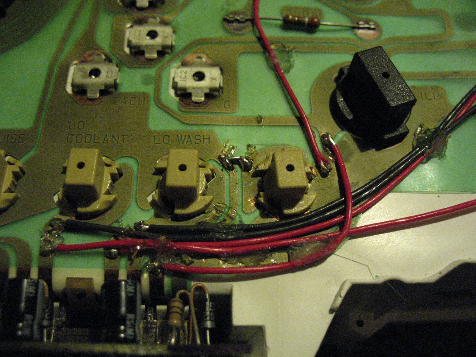
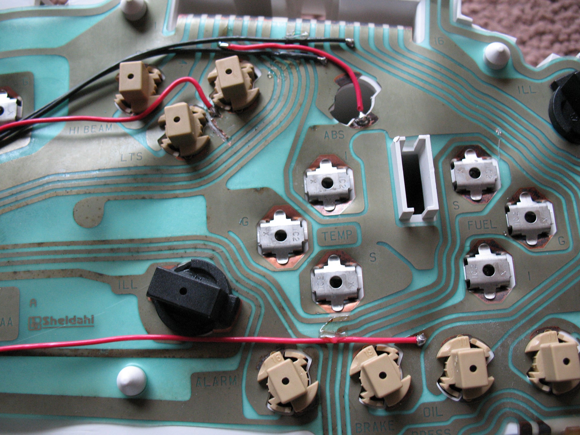
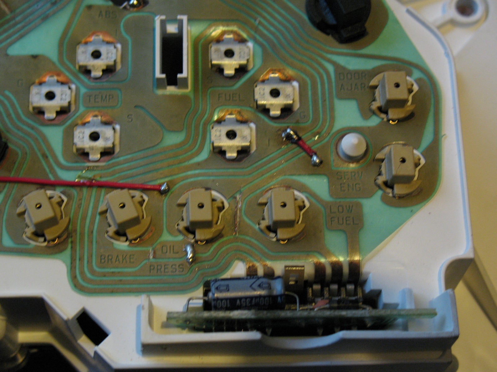
The above image shows the circuit that corrects the polarity on the seat belt indicator lamp, enabling it to function.
The extra splices are from where I found the switched wire was a ground, not hot, when the bulb already had a hot common lead to it.
I think that covers it all... In the 10 years since I originally did this to my cluster and the time of this re-post, I haven't had any issues with the mods. Red and black wires mean nothing as far as whether they're carrying ground or +12V; I just used what I had handy.
My whole reason for doing this is because I wanted the 8k tach without having to buy custom faces, which I already tried a couple years prior and was never satisfied with. I was originally planning on using the SHO cluster whole, unmodified, but I was getting too much of a headache mapping out how to repin the harness for it. So I gave up on that, thinking I'd have better luck using the stock cluster and simply rerouting the circuits for the lights.
As I alluded to before, I painted the backs of the faces yellow so they'll light up green at night. I also did the 'cut and paste' of the left-most lights (door ajar/SES) so the car icon has two doors, not four.
It is also possible to upgrade to the 8000 RPM tachometer. Trying to install the SHO cluster won't work directly because the circuit pinouts are almost all different. I determined that it is more reasonable to repin/rewire the stock cluster for the SHO gauges than to repin the SHO cluster for the MN12. The list of wires to move was 20+ items long, and I'm not 100% sure that some of the circuits use the same signal inputs. Putting the SHO gauges into the MN12 cluster does work, however; in order to ensure the correct indicator lights up, it is necessary to either rewire the cluster for the new warning light positions, or use custom gauge faces.
I previously tried using custom gauge faces, but was unsatisfied with the quality of them and opted to retrofit the gauges with the original SHO faces. The 96-97 SHO gauges are black like the MN12's; the 98-99 faces are white.
Here's the plan of attack. I numbered pins from 1-32 from L to R while looking at the back of the cluster:
Remove pin #3 white/light green O/D off
Remove pin #4 black/light blue T/A off
Remove pin #20 dark green/light green Seat Belt
Remove pin #28 pink/white Brake
Remove pin #29 white/red Oil
Cut trace to LO WASH bulb; run wire from module to seat belt bulb trace
Cut trace to LO COOLANT bulb; run wire from module to BRAKE bulb trace
Install pin #29 white/red wire to slot #3
Install pin #28 pink/white wire to slot #4
Install pin #20 dark green/light green wire to slot #29
Install pin #3 white/light green to socket #9 not used; add wire to unused bulb socket trace; cut plastic & install bulb
Install pin #4 to slot #28; cut trace before LOW WASH wire & install wire (before cut/harness wire of trace) to LO WASH bulb
That gets all the idiot lights lined up, save for T/A off lighting up as REAR LAMP OUT. If you're like me and have traction assist, you rarely pay attention to it so it isn't much of a concern.
HARNESS PREP
Remove plastic sheathing around both connector harnesses, and unwrap the electrical tape bundling them together
Remove pin #3 white/light green (O/D off)
Remove pin #4 black/light blue (T/A off)
Remove pin #20 dark green/light green (Seat Belt)
Remove pin #28 purple/white (Brake)
Remove pin #29 white/red (Oil)
Pins 28 and 29 need to be moved to the white connector side, and pin 4 gets moved to the black connector side
LOW COOLANT
Cut trace from LOW FLUIDS MODULE to LO COOLANT bulb
Cut trace #28 BRAKE between bulb socket and pigtail socket
Run wire from LOW FLUIDS MODULE trace #4 to bulb side of trace #28
LOW WASHER
Cut trace from LOW FLUIDS MODULE to LO WASH bulb
Cut trace between LTS bulb and S BELT bulb
Run wire from LOW FLUIDS MODULE trace #5 to lower/right trace of S BELT bulb
Run wire from +12V key on trace #27 to cluster trace #20 S BELT bulb
ABS (Option)
Run wire from ABS bulb/cluster trace #26 to LO COOLANT bulb side of trace
O/D OFF
Run jumper wire from +12V key on trace #6 to top/left contact of unused bulb socket
Cut GROUND trace around bottom/right contact of unused bulb socket to isolate contact
Run jumper wire around newly isolated contact from GROUND circuit near ILL lamp to GROUND circuit near LOW FLUIDS MODULE
Run wire from unused cluster trace #9 to bottom/right contact of unused bulb socket, install pin #3 white/light green in position #9 of pigtail
Cut hole in circuit plastic using cluster hole as a guide; scrape away plastic over contacts to provide electrical contact for bulb
Install spare bulb into socket
T/A OFF (option)
Run wire from LO WASH bulb trace to vehicle harness side of cluster pin #28
Install pin #4 black/light blue into position #28 of pigtail
* The 8k tach face in this position reads "REAR LAMP OUT", which was not used in the SHO cluster. Preferring a seamless, clean look, I chose to wire my T/A off light here. *
SEAT BELT
Install pin #20 dark green/light green into position #29 of pigtail
Cut trace #27 immediately before "OIL" text and before the "Y" splitting the trace to anti-slosh module and SES/Ajar lights - making sure to leave continuity between the SES/Ajar lights and the anti-slosh module (see picture)
Install bypass wire from trace #27 near fuel gauge "I" text to trace #27 to trace feeding anti-slosh module and SES/Ajar lights
Add wire from newly isolated trace on bottom side of OIL PRESS bulb to ground (trace with PRESS)
OIL PRESSURE
Install pin #29 white/red into position #3 of pigtail
BRAKE
Install pin #28 pink/white into position #4 of pigtail
The above image shows the circuit that corrects the polarity on the seat belt indicator lamp, enabling it to function.
The extra splices are from where I found the switched wire was a ground, not hot, when the bulb already had a hot common lead to it.
I think that covers it all... In the 10 years since I originally did this to my cluster and the time of this re-post, I haven't had any issues with the mods. Red and black wires mean nothing as far as whether they're carrying ground or +12V; I just used what I had handy.
My whole reason for doing this is because I wanted the 8k tach without having to buy custom faces, which I already tried a couple years prior and was never satisfied with. I was originally planning on using the SHO cluster whole, unmodified, but I was getting too much of a headache mapping out how to repin the harness for it. So I gave up on that, thinking I'd have better luck using the stock cluster and simply rerouting the circuits for the lights.
As I alluded to before, I painted the backs of the faces yellow so they'll light up green at night. I also did the 'cut and paste' of the left-most lights (door ajar/SES) so the car icon has two doors, not four.

