MHS PI H/C Tuning

theterminator93

Administrator
Staff member
Joined
Sep 12, 2023
Messages
1,198
Location
North Ridgeville, OH
Vehicle Details
1997 Thunderbird 4.6, 1998 Mark VIII LSC
Country flag
Originally started on 2/6/13.

Today I took advantage of the dry roads and sunshine and got the car emissions tested. Now that beating that deadline out of the way, I can take some time to sit back and breathe!!!

Now I need to spend some time and get the idle smoothed out and figure out why my STFTs are showing me at 12-14% lean...
 
General Zod said:
uh-oh!

someone needs to datalog.....
Yeah. It's interpreting the logs I need to work at most; time to whip out the LaSota tuning manual.

I haven't changed the intake set up or MAF/MAF transfer since I was running Don's dialed-in tune for the previous combo, so I can rule out the transfer being off causing the problem since the STFTs were ±4%. I'm wondering if perhaps it's related to the injectors I've got on the car; I might throw the 24s I had on the car before back on and reload the previous injector settings. I doubt I'm maxing out the 24s with this setup anyway.

Edit: I e-mailed MHS again about what heads I actually have and heard back this time. I have stage 2 heads but the valves are the 1mm oversized stage 3 valves. Good to know!
 
General Zod said:
What injectors do you currently have on the car, and are the STFT AND LTFTs showing identically on each bank?

They're red EV6 style 30#. I used the 30# value file in the root of the injectors value file folder.

I have thought about the possibility of a vac leak. I don't think I missed any lines when I put the top end back together but I'll definitely give it another good run-through.

The LTFTs at this point are both 1.00, the STFTs are nearly identical on both banks, there's about a 2% difference between the two.
 
General Zod said:
Did you make sure to input the voltage offset for those injectors?

To see if you have a vacuum leak quickly, set it to run open-loop by disabling the adaptive fuel table, cap off every single vacuum port on the intake manifold (except fuel pressure regulator). If your STFTs then hover abouts 1.00 as they should, the you do have a vacuum leak. This way (of disabling the adaptive fuel table) frees you from having to look at both for total correction, since total correction will now be easily visible in the STFTs, and them alone).

Or you could just use a vacuum gauge on the manifold. :)

Also, make sure you don't have any exhaust leaks---these will "show up" as lean. Primarily check the manifold-to-downpipes junction or any other junction that may have been disrupted in the installation process.

Yeah, all 5 values got changed when I loaded the value file. I just loaded the crank fuel pulsewidth tonight since I noticed I missed that one... I do know my alternator is on its way out though - only puts out about 12.4V at idle...

I did a low-tech vacuum leak test this afternoon by disconnecting each line at the plenum and sucked on them. I found the EVR solenid was leaking a little so I unhooked the lines from it and plugged the red one - no more leak from that. The evap and brake booster lines were fine though. Even after capping off the leaky EVR solenoid my STFTs are still showing an average of about 9% lean. LTFTs are zero (I keep reflashing minor changes to the tune every other startup...).

Checking the actual AFRs with the wideband shows that the fuel trims' correction factor is correct. 1.0 lambda pretty consistently in closed loop.

I tightened up the downtube bolts as well. What would be the next step here, go ahead with the cap off all of the vacuum ports (save the FPR) and check the fuel trims, or go back to and try out the 24# injectors? I am rather hesitant to mess with the MAF transfer function.
 
General Zod said:
there's only one sure fire way to rule out all vacuum leaks, and that's to cap off all the vacuum ports. For the FPR, you'll have to run a separate vacuum line, since both the FPR and the EGR solenoid share the same interface at the plenum (the double red tubes that merge into one connector). The only other possibility is intake manifold gaskets. If you cap off all vacuum ports, and you still see STFT corrections, you can hook up a vacuum gauge to one of the ports to see if the intake manifold gaskets are leaking.

Aside from that, how are the conditions of the injectors? were they brand spanking new? are they 30 lb/hr @ 39 psi or 30 lb/hr @ 43.5psi? if the latter then that means that they are "behaving" smaller than they would be @ 43.5psi. this could easily account for 5% or greater flow discrepancy when used in a fuel system with less pressure.

Well I did the research and found the rated flow numbers are 30 lbs/hr at 43.5 PSI - and the last time I checked my fuel pressure it was just about 40 KOEO (going to check the actual pressure this afternoon for more precise numbers KOEO and KOER). They're used/cleaned injectors.

BOSCH LBS/HR CC/MIN GRAMS PSI BAR
0-280-155-759 30 315.3 226.8 43.5 3
 
NetKeym said:
Hey, I have a set of those! Those 30 lb injectors actually came from a Volvo 5-cylinder, but they are nice looking.

I hope your issues get worked out and those injectors work well for you - because then I'll know the set I have will work well for me!

General Zod said:
BINGO! How did I know? Perhaps because I'm awesome like that. :biggrin:

The numerical factor for changes in fuel pressure is

Sqrt(current_pressure/rated_pressure)

So you were right in hesitating the mess with the MAF-- that should only be done in certain cases that actually merit it because an incorrect engine load causes more issues later on down the road.

Apply the correction factor to all 5 injector parameters. To properly set the crank fuel table, use this correction factor...

Orig_low_slope/new_low_slope

...and apply it to the whole table. This is due to the fact that while cranking, the injectors' flow is characterized by the low_ slope fuel scalar more than anything, because of the short pulsewidths.

OxmanWI said:
Congrats on getting her up and running, long time coming for you and just in time for the spring and summer. Sounds great!

Thanks Josh. I was planning this to be the "winter mod" of 2012-2013, plus with the Ohio BMV all "E-Check!" on me I had to get the thing finished before my birthday.

GM, yup - 39PSI on the dot at idle, then it fluctuates a little as I was playing with the throttle between 36 and 42. Time to edit some injector tables...
 
General Zod said:
39 psi with the vacuum removed from the FPR right?

No actually with vacuum. Without vacuum it's a touch over 43 PSI.

If I do the math, my 30# injector file was actually set with a high slope equivalent to 32#/hr. Since the injectors are rated for 30 at 43.5PSI and I'm actually at 39, that's a bit over 10% lean.

Doing some logging just now, at idle the STFTs switch between .96 and 1, but if I do free revs at 1500, 2000... 3500 RPM they indicate it's ~20% rich. Clearly I've got a lot to learn. :confused:
 
General Zod said:
give me the run down on your entire fuel system. fuel pressure should be in the low/mid 30s at idle with vacuum on the FPR, and 39psi without vacuum on the fuel. Anything else indicates issues. Also what do you have for a maf?

190 lph Walbro in the tank. Stock fuel lines, stock fuel rail, 43.2 or so PSI without vacuum, 39 with. Time for a new FPR?

The MAF is the 80mm 02-04 GT style. Air box and tube are of the same style as well.
 
General Zod said:
yea I would say so. even with your cams you should still have some kind of vacuum at idle, leading to a sub-39 psi fuel pressure.

Okay, I'll get that replaced as well as the EVR solenoid. Then I tune my injector data to reflect the flow of the injectors at rail pressure without vacuum?
 
General Zod said:
correct. Without vacuum gives you the true pressure differential across the inlet of the injector to the outlet of the injector. It is this pressure differential across the two ends that needs to be 39psi.

The alternate way of checking true pressure differential is to leave vacuum on the FPR while getting rail pressure, and simultaneously get the vacuum reading off the manifold in in-Hg, then convert it to psig, in order to "add" it to the rail pressure.

The_coop_08 said:
Cant wait to see what numbers this puts down now!

Fuel pressure now is spot on 39PSI no vacuum and about 35 PSI at idle. Fuel trims idling and cruising are within .05 of 1 on both banks.

Did a little idle tweaking and have it loping pretty stable at 700 RPM in drive and 800 in neutral. WOT A/Fs on the untweaked MAF transfer were a little rich (about .78-.80 lambda and my target is .85-.86) so I've revised the MAF transfer function and will check the results tomorrow.

Getting there... :biggrin:
 
General Zod said:
Thats what I'm talking about. :thumbsup:

So did you end up altering the injector values or going back to standard 39psi injectors?

I altered the injector values to reflect the flow at 39 PSI (28.4#/min) and left them on the car. What can I say, I like red, lol. :)

I've still got some work to do at idle though... darned thing stalled on me out of nowhere as I was pulling into the garage yesterday. And go figure, I had stopped logging JUST before that happened too. :facepalm:

One thing I would like to figure out with idle which I've kind of placed on the back burner for now...

When the car is cold (e.g. yesterday morning the ACT and ECT was about 34 degrees), it obviously starts out in open loop and my A/Fs are about 13:1 as commanded in my fuel tables. Idles perfectly. As soon as it switches to closed loop about 40 seconds after startup, the A/Fs go off the chart lean and the car almost dies, then recovers after the RPM dips below 500. The closed loop idle after that is smooth and doesn't surge. Any thoughts on where I should start looking to sort that out?
 
General Zod said:
Log the stft's and ltft's along with O2 voltages.

Grog6 said:
I'd bet the o2's aren't warm yet; IIRC, they show lean until they come up to temperature.

You may need to extend the warm up time another 30 seconds. :zshrug:

I don't see that effect, but my warm up time is 120 seconds; I left it at stock this winter.

General Zod said:
that's what I was thinking. I think looking at the raw O2 voltage signal will clue us in as to what's going on.

I just tested a delay of about 120 seconds after startup and it behaved much better. It surges a little but I think that's because my airflow model is still off at the higher-than-normal idle RPMs. My WOT A/F is right where it needs to be now at .85-.87 lambda and my cruising O2 bias switches between 1.00 and 1.03 lambda. :biggrin:

This is slowly starting to come together...

One thing I've noticed is that the peak air mass is about 26#/min. which I hit at about 5200 RPM and maintain through the rev limit. I've also noticed VE peaks at about 90% at 3800-4000 RPM but decreases steadily to about 70% by 6300 RPM. I am going to assume that's normal/caused by the PI intake...

GM, do you have an idea of what MBT spark for a 10.4 CR PI head swapped npi block looks like? I've loaded the value files for the PI heads/npi block with 93 fuel and borderline/max allowed/modifier tables were changed but the MBT tables weren't. I'd like to start logging/adjusting my spark to see how close I can get to MBT across the board, but it's difficult to do when your MBT tables are the same as they were for 9.4:1 CR with 87 octane. :roll:
 
General Zod said:
The mass airflow rate is a bit low. How much did you lower the MAF transfer function in that area? I mention because I hit ~31 #/min with stock PI heads/npi block/Crower stageII-ish cams/SVO intake. Even with a PI intake, I hit around 28 #/min in springtime weather. The MAF transfer function signal is used in the #/min calculation---if you had to adjust it more than 2-4%, then something else might be amiss that we could look into.

VE looks normal. Obviously a higher flowing intake would help make more power up top, and thus VE would stay afloat to a much higher percentage near the rev limit.

Don't worry about MBT spark. It is used primarily for calculating engine torque output for transmission operation. The MBT equivalent is the Max Allowed Spark table. It is essentially MBT but modified to take other factors into account. So you wanna run as close as possible to Max allowed without detonation.

Yeah, I ended up adjusting it more than that. Close to 10% actually. Before I adjusted the transfer function on my first run I was going as low as a .78 lambda but the airflow was nearly 29 #/min.

Hm... something is definitely off here now that I'm looking at this. I'm looking at my actual A/Fs just after startup on the last three starts and it's about .07-.1 leaner than what's commanded (e.g. commanded lambda .8 but actual .9). Up top that's the opposite; before I altered the transfer function it was running almost 10% richer than commanded (~.78 when .86 commanded).

I'm thinking I should turn off closed loop and check my actual:commanded AFs across the entire airflow range?
 
General Zod said:
Always turn off closed-loop when adjusting fueling. Speaking of which, how do you personally turn it off? Just gotta make sure we're on the same page.

I'll go in and max out the time delay for closed loop table, unless there's a better way to do it. Adaptive learning is already turned off as well.
 
General Zod said:
Turning off adaptive is enough. LTFTs should always show 1 when doing so.

Okay yeah, adaptive has been off since Don tuned the car last year and my LTFTs are 1. BTW if you wanted to split the thread from post 154 and drop it into the EEC tuning section go for it - it might make more sense since at this point the thread seems focused on my attempts at the tuning of the combo.

How do I figure out when the PCM switches from low slope to high slope, is there a convenient PID I can add to my logs that will tell me which slope the PCM is using? I know it's got to do with the break point, but I'm not sure how to convert that to a usable number and how to interpret that number... Is it possible my low slope isn't high enough and my high slope is too high? :confused:

Tuning seemed much easier when I was just playing with shift points, lol.
 
General Zod said:
You can log the low_slope/high_slope/breakpoint/offset in the Gen-II Livelink. Unfortunately I never got to log these to see what kind of numbers show up because I parked my car long before this newer Livelink came about---they weren't available in the older LiveLinks.

Go ahead and log them and then send me the datalog.

There is a way to calculate if the injector is called to inject fuel past the breakpoint pulsewidth and into the high-slope region, but lets see what those PIDs show first before we go into manual over-ride, lol.

As an extra, I would first plop back in the stock 19lb injectors. With these, the fuel delivery model would be 100% intact with the stock injector data. This would allow you to fully adjust the MAF transfer as much as needed so long as it correlates with the O2s/wideband data. You're basically using one calibrated aspect (stock injectors) to precisely calibrate the other (the MAF transfer function). Once the MAF transfer function is dead-on, then there will be no need to further adjust it---you can then focus on the 30lb injector scalars/tables knowing the air-flow model is 100% correct.

Well I finally plopped the 19s in yesterday afternoon. Sure enough, it's doing the same thing as it was with the 30s. Running a bit lean at idle, then at 200 counts it's about where it needs to be, but then as you increase airflow it gets richer. Obviously going to have to spend some time and dial this in. By chance do you have a value file for the 02 GT MAF GM? I'd like to compare it to what mine looks like currently. I didn't see anything obviously labeled as such in the value files folder.

The other strange thing I've noticed, which I admit I haven't spent a lot of time trying to track down yet since I've been focused on other things, is that getting it to start is a bit of a challenge sometimes. I'm wondering if there are any obvious things to look for before I start beating my brain against the wall troubleshooting. Usually it fires right up with no hassle, but sometimes it will turn over, stumble at about 400 RPM then die a second later. If I try to crank it again it just cranks endlessly - but if I crank it at WOT it fires right up. All the sensors are new except the TPS (which I have a new one ready to go on), and I've never been unable to start it.
 
General Zod said:
theterminator93 said:
Well I finally plopped the 19s in yesterday afternoon. Sure enough, it's doing the same thing as it was with the 30s. Running a bit lean at idle, then at 200 counts it's about where it needs to be, but then as you increase airflow it gets richer.
It's probably doing this because you no longer have the same transfer function after adjusting it.
theterminator93 said:
By chance do you have a value file for the 02 GT MAF GM? I'd like to compare it to what mine looks like currently. I didn't see anything obviously labeled as such in the value files folder.
It is under the MAF folder, but it is labeled as 9698gt.mvf. Load this for the 02 gt maf, and then adjust it if needed (unless you need to adjust more than 10%). Once it is set, it is set period, so long as delta fuel pressure remains at ~40psi. Then you can go back to the other injectors leaving the airflow model intact.
theterminator93 said:
The other strange thing I've noticed, which I admit I haven't spent a lot of time trying to track down yet since I've been focused on other things, is that getting it to start is a bit of a challenge sometimes. I'm wondering if there are any obvious things to look for before I start beating my brain against the wall troubleshooting. Usually it fires right up with no hassle, but sometimes it will turn over, stumble at about 400 RPM then die a second later. If I try to crank it again it just cranks endlessly - but if I crank it at WOT it fires right up. All the sensors are new except the TPS (which I have a new one ready to go on), and I've never been unable to start it.
what is the ISC cranking duty cycle set to in the tune?

Stock:

Here is the value file transfer on the left vs. what I had before (right). Definitely looks like it was off by a good margin.

General Zod said:
max out the crank isc duty cycle table

if yo still have trouble crankin it up, you can look at the fuel in the crank fuel table and/or the crank fuel decay table (forgot the name). Recreate the condition, and experiment with 5% less, 5% more, etc, etc.

first max out the ISC duty cycle to see how it behaves.

Also, check how many #/min of airflow is actually going across the closed TB while it is idling.
 
March 28, 2013

Finally got around to doing some more tuning this afternoon.

Maxing out the crank ISC duty cycle seems to have done the trick - about a dozen startups at various ECTs and it never gave any trouble.

As far as the MAF transfer, I loaded up the value file and compared commanded to actual A/Fs while in open loop. Pretty consistent across the board, as a whole it's about 3% too lean from idle up to 800 counts. I still need to check my revised transfer function before I put the 30# injectors back on and fine tune for those, but I think I'm pretty close now.

March 29, 2013

Finally got the A/F dialed in. Peak airflow comes in around 29.5 lbs/min. Average STFTs over a 6 mile city test drive were .988 and .997, WOT A/F is between 12.3 and 12.5... I'd say I'm in business. :biggrin:

Thanks GM for the pointers, for a while there I felt like I had no idea what I had gotten myself into.

Now I must decide if I should play with spark...

May 10, 2013

Soooooooo I've started messing around with injector delay. I've done the calculations and have my cam's valve timing events based on crank degrees:

0, TOP OF POWER STROKE
119, EXHAUST OPENS
180, BOTTOM OF POWER STROKE. START OF EXHAUST STROKE
250, EXHAUST FULLY OPEN
333.5, INTAKE OPENS (EXHAUST STILL OPEN)
360, TOP OF EXHAUST STROKE. START OF INTAKE STROKE. BOTH VALVES OPEN.
381, EXHAUST CLOSES (INTAKE STILL OPEN)
466, INTAKE FULLY OPEN
540, BOTTOM OF INTAKE STROKE. START OF COMPRESSION STROKE
598.5 INTAKE CLOSES (BOTH VALVES CLOSED)
720 TOP OF COMPRESSION STROKE, START OF POWER STROKE

And I'm doing the number crunching based on this post: http://eectuning.org/forums/viewtopic.php?t=11334

The goal, as I understand from having read a few threads on the SCT forum, is to have all of the needed fuel sprayed on top of a closed intake valve so as to let it evaporate for maximum atomization when it is drawn into the cylinder. At high RPM/load conditions such as WOT, knowing the pulsewidth is necessary to figure out how late you can finish injecting so as to be sure the fuel needed is delivered before the intake valve opens, but after it closes. That is a total crankshaft duration of 455 degrees. With my injectors and 100% load, the max. pulsewidth will be 15.5 ms with a 12.4:1 AFR. At 100% load and 6000 RPM, the crank will rotate 558 degrees in the time it takes to inject the needed fuel - which would necessitate fuel be injected from the time the valve closes through the first 76.5 degrees of the intake stroke (from 598.5 degrees through 436.5). Since I'll likely never see more than 90% load at 6000 RPM the "theoretical" max. pulsewidth would be 14ms, or 504 crank degrees (injecting fuel from 598.5 through 382.5, or into the first 49 degrees of the intake valve open event).

Anyway, to the point of this post. If I follow those calculations to the letter I should be able to come up with the optimal fuel injection finish points, in crankshaft degrees, for every load/RPM combination such that the fuel starts injecting onto the closed intake valve immediately after it closes and sits there for the entire duration it is closed, soaking up as much heat as possible and becoming as atomized as is possible.

The questions here are:
a) Is there a point when the fuel is sitting on the valve TOO long (e.g. at low RPM and pulsewidth conditions)? Should I have it wait a short time after the valve closes to start injecting fuel? E.G. at 15% load and 800 RPM (my idle) if I started injecting as soon as the valve closed I'd have an injector delay of 610 degrees, and the fuel would sit on the back of the intake valve for .092 seconds.
b) Will there be any issues if fuel is spraying onto the valve as soon as it closes and continues to spray after it has opened again (in the example above)?

The stock delay table has fuel delivery completing at 112 degrees at 75% load/1700 RPM and up, which with my current delays (stock) would mean fuel delivery begins somewhere around 413 degrees (or later) - still in the last 2/3 of the intake open event of the previous rotation's intake stroke! :eek:

Sorry for the long winded post and if it isn't very coherent. I'm usually not up this late but I got caught up in the thrill of crunching numbers. :diablo:
 
General Zod said:
You do know I developed and posted about, a spreadsheet that does all this automatically? Lol

Even then, ALL the fuel will not sit still on the back of the closed intake valve. I'll post a quote I found on another forum concerning this tomorrow.

In your case, you'd benefit more from generating a model that specifies the end time based on a necessary start time sufficiently late that no unburned fuel goes out the exhaust during the overlap portion.

I saw your last post in the prp forum thread that linked to the eectuning thread where you mentioned the spreadsheet. In fact I've been so caught up in crunching numbers it totally escaped me to put 2 and 2 together to think about that. I guess this means I should go to bed. LOL

Are you referring to the fact that some of the fuel will get drawn out the still-open exhaust valve as soon as the intake opens?

Oh well. I've got my 100% load pulsewidth at WOT A/F calculated so the rest is just multiplying that figure by .006 and the engine RPM and load factor, then adding that to the intake valve close event and subtracting 720 (barring adjusting the pulsewidth to reflect the stoich A/F). Easy-peasy. As long as "earliest possible" isn't too late or too early, I'll run with it and see what it does.
 
Bill H said:
I'm sure you know this but EEC analyzer (EA) does all of this based on your logs. A license is not all that expensive given how much you are into this. If you spend more than a couple he's on just this topic, I'm sure your "billable rate" would justify it. :)

http://www.eecanalyzer.net/images/screenshots/EA/CAM.png

Thanks Bill, I've heard good things about it and I'm definitely considering it, but for now I've got a few spreadsheets that are giving me what I need. ;)

Since there really is no way to avoid having fuel spraying during overlap (8 degrees at .050 in my case) at high load/RPM conditions should I presume that having the fuel delivery complete in those cases as late as possible on the intake stroke, so as to maximize the amount of fuel delivered post overlap and theoretically minimize draw-through?

I've read that it's not as much of a concern at low load/RPM conditions because scavenging isn't as much of a factor when there isn't as much air moving, so my thought is to start injecting fuel right as the intake valve closes, which should maximize atomization due to evaporation.

The alternative is to try and inject such that the pulse finishes as late as possible in the intake valve open event to minimize possible loss through the open exhaust valve. E.G. set the table to complete injection by the time the valve is halfway between its max. open and .050 closing event.

I guess I'll just have to try it both ways, look at the logs, and experiment. :zshrug:
 
Preliminary results of a short test run. Having the injectors fire right after the intake valve closes definitely shows a difference in driveability and throttle response compared to having them fire before the intake valve closes. If they fire after the valve closes and the fuel sits on the valve there is a definite lag in throttle response compared to stock or having them fire fuel directly into the incoming air charge with the valve open (although I think this can be reduced if the time the fuel spends on the valve is reduced). The fuel trims also show about a 3-4% richer mixture with a valve open spray event compared to a valve closed spray event (which can be expected due to fuel getting sucked right out of the exhaust valve after the intake opens). In theory that would translate to better fuel economy since less fuel is being wasted out the exhaust. I don't have any comments or data on high load/rpm behavior at this time since I didn't do any (near) wot runs.
 
General Zod said:
theterminator93 said:
so as to maximize the amount of fuel delivered post overlap and theoretically minimize draw-through?
now you're thinking.
theterminator93 said:
so my thought is to start injecting fuel right as the intake valve closes, which should maximize atomization due to evaporation.
you're right, it maximizes atomization, but with cams like yours that have a lot of overlap due to a low LSA, some of that beautifully atomizied fuel goes right out the exhaust valve! lol
theterminator93 said:
The alternative is to try and inject such that the pulse finishes as late as possible in the intake valve open event to minimize possible loss through the open exhaust valve. E.G. set the table to complete injection by the time the valve is halfway between its max. open and .050 closing event.
no need to make it inject "as late as possible". As soon as the exhaust valve closes, you can inject fuel to minimize the loss. But I'll clue you in on a little secret: Intake port velocity has a maximum about 10° before the intake lobe centerline ;) If your injectors are large enough, you could possibly inject all the fuel needed (under all operating conditions ) right during the moments the air velocity in the port is greatest to maximize the homogeneity of the mixture.
theterminator93 said:
Since there really is no way to avoid having fuel spraying during overlap (8 degrees at .050 in my case) at high load/RPM conditions
See underlined text in above ;)
theterminator93 said:
Preliminary results of a short test run. Having the injectors fire right after the intake valve closes definitely shows a difference in driveability and throttle response compared to having them fire before the intake valve closes
This is because the air velocity is pretty much zero at this point, or worse: there is intake reversion going on so a lot of that fuel isn't even making it into the cylinder. Quite the opposite scenario compared to injecting before/during the intake cycle where there is still vacuum in the cylinder.
theterminator93 said:
The fuel trims also show about a 3-4% richer mixture with a valve open spray event compared to a valve closed spray event
It's not really that it's richer IMO...I think this has to do with tuning the MAF transfer function with standard injector delay settings. Remember, before, some of that air/fuel was going out the exhaust, so that tricks the WB into showing "lean". Hence you inadvertently increase the maf transfer to bring it back down to stoich---and now that extra air/fuel that is not being lost out the exhaust before being burned, it brings the mixture to the other side of stoich--a bit rich.


PS: google on how the 5.0 Coyote mustangs do their fuel delivery with regards to their injector delay settings.

After I posted my thoughts late last night I came to that realization - so I'm starting injection just after the .050 close event of the exhaust valve on the assumption that by the time it takes for fuel to actually reach the combustion chamber the exhaust will be closed. If fuel delivery at a given pulsewidth will take longer than the time the intake is open, I limit the delivery finish point to where the intake valve is about halfway closed on its way shut. Thanks for that port velocity info, I'll put it to good use. :)

Thanks for mentioning that - I was thinking about this too. So if I understand correctly that does indeed mean that the MAF transfer is a tad too high (rich) as a result of the fuel draw-through/stock delivery timing causing some fuel to be lost out the exhaust. I wanted to re-verify my AFRs anyway, this gives me a reason to get started futher dialing in the MAF transfer sooner than later. :)

Edit... Now that I think back, I think when I was initially dialing in the transfer function it was coming up as "universally" 3-5% low. Now I guess I get to reverse most of that... :roll:
 
General Zod said:
The exhaust 0.050 closing event is no where near "late enough" at low RPMs because the residual exhaust pressure is still somewhat "sketchy" at this point. Yes there is some draw-through, but not the entire time---it is mostly during the latter part of the closing event where the intake valve is well above the seat.

The velocity profile is continually changing though. On average, at low RPMs it peaks about 10° before ICL, at mid RPMs the velocity peak coincides with the ICL, and at later RPMs it peaks about 10° after ICL.


It's a very tricky situation with large cams because at low RPMs, there is reversion both at intake opening (due to little to no exhaust scavenging) AND at intake closing (due to not enough inertial wave tuning from the incoming air mass). These intake reversion effects start diminishing once RPMs start climbing and the air velocity is carrying much more momentum at the right times.

Well, after the first bit of driving with the new injector timing loaded up I can say I've definitely noticed an immediate increase in fuel economy. With ambient temps in the low 60s this morning I was seeing instant fuel economy in the neighborhood of ~26 MPG cruising at 65, whereas before it was closer to 23-24 in 70-75 degree air. Amazing what happens when you're not dumping unburned fuel out the exhaust. :)

Now to get the MAF transfer dialed back in, then figure out my CFSO TC bucking problems...
 
General Zod said:
So where are you starting/ending the injection after all?

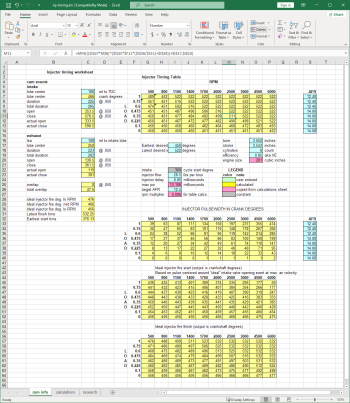
Here's the output from that spreadsheet (I stuck it in the root of my server for you to look at if you felt so inclined):

1695669337961.png

The timing is based on having the pulsewidth centered around the "ideal" time to have all the fuel delivered. If the pulse would start before the exhaust valve close event it would set that to the earliest pulse start time, but only so far as the point where the pulse is finished before the intake valve is halfway closed on the closing event.

I copied the last chart directly into advantage (I already had adjusted the ynorm for that table before I prepared the spreadsheet).
 
General Zod said:
Yea I had seen it but wasn't sure if you had modified it any further. So you are using the 0.050" events as actual opening and closing events?

My "preferential earliest start time" is 376 degrees, which is 5 degrees before the .006" exhaust close event. My "absolute latest finish time" is 532 degrees, which is the intake halfway closed after the peak lift point. Any "actual" events are measured at .006 lift.

The formula is as follows:

a = pulsewidth
b = preferred delivery time
c = latest finish time
d = earliest ideal start time

min(max((b-a/2);d)+a;c)

This way it chooses the highest value between the calculated injector pulse start and desired start time, then compares that result to the injector finish point and uses the lowest number.

If the pulsewidth is too long to fit between "preferential earliest start time" and "absolute latest finish time" I hold true to the finish time and let the pulse start earlier. This way all the fuel intended for a particular stroke is delivered while that stroke is still drawing in air/fuel. The downside is some fuel is sitting on the intake valve as it opens. The thought there is that the amount of lost fuel can be reduced in those situations by minimizing the amount of fuel sitting on the valve when it just begins to open. Short of getting bigger injectors, the only way to do it is to finish the pulse as late in the intake valve open-close event as possible.
 
General Zod said:
Oh ok I see what you did now. You can always go to bigger injectors to shorten up the PW dramatically in order to inject all the fuel, under pretty much any circumstances, during the peak airflow point (or at least very tightly centered there about) for even better fuel economy.

Kinda makes ya sad though doesn't it-----"tuners" dont normally do stuff like this and there are countless cammed mod motors out there getting truly sucky fuel economy and emissions due to unmodified injector delay tables, lol.
nickmckinney said:
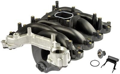
Something I can add is that I port match plastic OEM V8 intake manifolds and found something interesting. Pulling a strong vacuum at the plenum opening and masking tape over all the ports other than the one being worked on I find the plastic shavings completely covering the masking tape on all 7 other ports right away. I wonder if the fuel really all stays on the valve in a running engine. Here is a picture of the manifold I port, you can see the long runners and I mount the biggest shop vac to the center plenum opening with a modified stock upper elbow.

1695669424569.jpeg

A little quote I found from Nick. Makes ya wonder.....

Grog6 said:
Harmonics in the intake plenum would be my guess. :rofl: (j/k)

Actually, a bit of Vacuum makes strange stuff happen:

I'd bet that anything you evacuate in a similar circumstance will be covered with shavings. Feet of separation should not be an issue, as long as several inches of vacuum is maintained.

Once the air is out of the way, things bounce in straight lines, modified only by gravity; they can bounce way further than you would think.

Particles in a partial vacuum like this will coat every surface; a very useful fact, if you think about it. :)

General Zod said:
Yup, I'm betting the miniscule amount of fuel that is sprayed into an already fine atomized mist while there is vacuum @ partial-throttle-driving, hardly has a chance to just plop straight down the intake port and just sit away, unperturbed on a hot intake valve with all the dynamics happening inside the intake manifold.

I was doing some reading on that the other day on the SCT forum. It doesn't look like there's a way to do it without access to the "hidden" functions that "regular" PRP users can't see...
 
Grog6 said:
Yeah, that's my thought too.

I'll PM Don and see if anything is available.

General Zod said:
I won't be able to do any testing until I'm up and running. What do you have to correct your speedometer? What gears do you have? Your SIG implies you have stock gearing.

I believe you have to purposely shift the N/V scalar in order to trick the pcm that you're going slower than you actually are, thereby avoiding the 3-4 shift . Naturally, you'd have to factor that into the shift/lock schedules and any other tables that are currently being used that rely on knowing vehicle speed. I'm just not sure which way the scalar would have to be shifted. A quick altering of it, along with setting the allowed corrections to zero and a corresponding datalog of the proper parameters should quickly reveal all the pertinent information.

Interesting concept; I can see how that could be made to work. Until we hear back from Don though I'll wait until someone else tries first... ;)
 
Grog6 said:
I sent an email offering to pay for info; that should make it less painful to answer.

I'm sure he gets lots of interesting email, lol.

I need to look into a speedcal, unless I break down and go for 20's. :biggrin:

Hey, no more needing ramps for oil changes, lol. (j/k)

I asked if there's no fix in the PRP, if a value file could be created; I'm sure his version of the SW is a bit different than ours. :)

I'd pay for a value file that fixes this. :)

I'd pay too, depending on price. I don't ever see triple digit speeds, but it sure would be nice to be able to rev out the motor when the car is on the dyno. :)
 
Don 95Vert said:
If someone sent me an email about this, I did not get it.

No way I know of to get past this limit - it involves a 5v signal and OSS output being the max the PCM 'knows' and that equals 127.5 MPH. I think you can play with N/V but that would mess up the rest of the shifts. If I knew, I'd tell everyone.

Word was Jerry W. had a fix for this, but I never saw it and have lost touch with him. I don't think he has done any tuning in a few years. People who may have it, are not sharing that info and it may not work on earlier vehicles. I think the person who said he had a fix was referring to automatic Mach 1's where the PCM is much more sophisticated.

When you start going that fast, maybe time to get a full manual VB - which I really hate for the street or a Bauman controller. Have one on our Gen 1 Turbo Lightning and it works well.

BTW: I usually answer emails same day, often within the hour - so if someone emails me and do not hear anything from me for a while, assume I did not get it.

I'll ask some other dealers who may have some info and if anything changes, I'll be sure to post it.

Don

General Zod said:
Don,

My idea was to use the fact that an actual NV higher than the tune NV causes shift the shift limiter to kick in earlier when no tune is present to correct the NV to what it actually is.

for a stock 96/97 4.6 mn12, the speed limiter kicks in at ~87mph, because the pcm thinks you're doing 106mph. What I wanted to do was "backwards", as in kind of like "make the pcm think you're going 87mph, when you're really going 106mph" sorta thing, just not to the same extent but enough to avoid the dreaded 127.5mph override 3-4 upshift.

What I came up with was this...

PCM_spd = Actual_spd * (Actual_NV/Tune_NV)

If you set Actual_spd= 87mph, Actual NV=52.4, Tune_NV = 42.5, then the PCM_spd= 107mph, which makes sense about where the speed limiter kicks in with 4.10s when the tune has not had the NV adjusted for the shorter gears.

In order for the PCM_spd to be lower than the Actual_spd ( to avoid having the pcm hit that dreaded 127.5mph number from hell), the ratio Actual_NV/Tune_NV has be numercally less than 1, which means that Tune_NV > Actual_NV.

So therein lies my idea: set the Tune_NV higher than Actual_NV, coupled with setting both NV learning scalars to 1 to avoid having the PCM shift the NV anywhere, and it will [should] scale down your actual vehicle speed down to what the pcm thinks is a lower speed by a factor of Actual_NV/Tune_NV

In my mind it seems like it would work, but obviously I have not done any testing to verify so.

Say for a car with 3.73s and an NV of 47.5 going 100mph, setting the tune NV to a maximum of 60 would lead to a pcm_spd of ~79mph, so approx. 20% reduction of speed as the pcm sees it. Therefore [hopefully] the shift/lock schedules would be reduced 20% to get everything "back in line". This is just an example of course, as such a drastic reduction in PCM_spd might not even be necessary.

Depending on tire size, there would be a limit on how short of a gear you could go and still be able to trick the pcm into thinking you're going slower. For a ~26" tire, the practical limit would be 4.56 gears in order to cause a 4% decrease in apparent speed. In which case I'm screwed because I'm using 4.88s, LOL.

There's always the OSS count....

Grog6 said:
Don, I emailed your business email from my aol.com account, I forget that it usually hits a spam filter somewhere. Sorry. :)

I've had the aol account since ~91, lol.


Thanks for the input, Don!
:)

General Zod said:
Don,

Do you know the actual formula that a 97 CDAN4 processor uses to calculate vehicle speed?

Don 95Vert said:
I don't know how that is calculated.

I DO have a way to prevent the OD shift at WOT though. I remembered it with the help of another SCT dealer with a better memory than mine. He jogged my memory - I hadn't used it for 5-6 years. Unfortunately, most Pro Racers have no access to those particular areas.

I did make a value file and have it. You won't be able to see the changes perhaps, but they'll be made. I cannot post it because at the time I was asked not to, so I won't. I did not 'discover' this method - this is 100% Jerry. But anyone who got their PRP or a book from me, can email and I'll send the value. Use it at your own risk, because I have NEVER tested it and am not 100% sure it works on all vehicles. It should though. If it doesn't, you may lose a tranny, so like I said - use at your own risk - consider it experimental.


don

Grog6 said:
Don, I bought your book, and have a cantidate tranny I can test it on.

It's either light on the direct clutch, or I have other issues. :) But it shifts fine at hard throttle. :)

If you'll email the value file to me, I'll see if I can get some track time next weekend. I'm G r o g 6 a t a o L d o t c o m, which will probably hit your spam filter if I do email you.

I can prove I bought your book if you like; I should be in your records. :)

I will offer a shameless plug for your book; it is the best info and tuning techniques I've found, and I've been reading everything I can find. :)

A question; as I'm using other value files, is there a best loading order? Like, load that one last?
.

General Zod said:
well that's pretty much what we're looking for. Chances are, if you're getting close to 127.5mph in 3rd gear, you ain't in part-throttle mode anyways. :tongue:

What if one was to buy a .mtf tune from you? Could we get the value file then?

Hi Don, could you send it to me as well? I'll send a reply to the string of emails we exchanged last year when we were doing business together to help you remember me. :)

Well GM, I guess now's the perfect time for you to finally bite the bullet and buy Don's book! :tongue:
 
General Zod said:
what I REALLY need to do is go to SCT headquarters and take Banish's advanced tuning classes in order to get calibrator level access and work on this stuff on my own. I know I can handle it, just a matter of time and money.

Threats. All the time, threats...

:tongue:
 

Similar threads

Back
Top