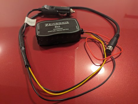
I’m duplicating this article that used to be on Innovate’s website but was recently deleted*
LC-1/LM-1 Integration into SCT’s Xcal 2
written by Steve Hulett
Download a PDF version of this tutorial
This guide will help you connect your LC-1 or LM-1 to SCT’s Xcal 2. It will also show you how to create the wiring, setup the software, and create the formulas for different air/fuel ratio ranges. It is not intended as an installation manual for the Innovate Motorsports equipment, but as a tutorial for interfacing that equipment with the Xcal 2. Please refer to manufacturer’s manuals for details, warnings, and other specific information.
Parts Needed
To set up your data logging system, you will need the following pieces:
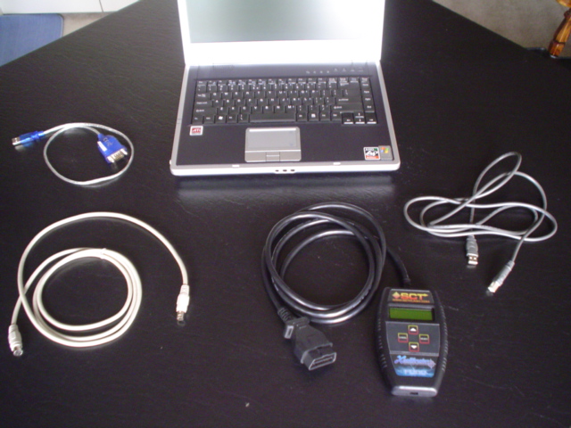
The Innovate Motorsports hardware uses a serial out cable to interface their LC-1 with a laptop computer, via the LM Programmer software. If your laptop does not have a serial port, you will need to acquire a USB to serial DB9 male adapter cable. These may be purchased from Innovate Motorsports or from your local electronics store.
Wiring
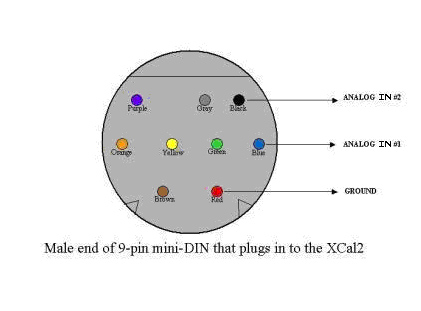
Please refer to the appropriate installation manual for specific instructions. I will go over the wiring briefly, because how you wire it will have consequences on overall accuracy that we want to avoid. Specifically, ground offsets. Not all 9 pin mini-din cables have the same color wires, make sure to reference the pin-out diagram below..
LC-1
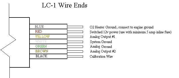
The red and black wires are explained well enough in the installation manuals. Ground wires are of the most importance here. The ideal ground in a car is always the engine block. To start, ground the Blue heater ground to the engine block. The Green analog ground and White system ground wires can be connected together, and then grounded to the engine block on a lug all by themselves. This is where you will also ground the Xcal2 9 pin mini-din cable’s Analog Ground wire.
We will be using three wires of the 9 pin mini-din cable from SCT. Analog In 1, Analog In 2, and Analog Ground. The blue SCT Analog In 1 wire will connect to the yellow Analog Out 1 wire. The black SCT Analog In 2 wire will connect to the brown Analog Out 2 wire, and the red SCT Analog Ground wire will connect to the ground spot mentioned above, where the Analog Ground and System Ground wires are grounded.
LM-1
The LM-1’s analog output cable has three wires. Red is analog output 1, white is analog output 2, and the remaining wire is the analog ground wire. It is ideal to run the analog ground to the engine block. This is where you will also ground the Xcal2 9 pin mini-din cable’s Analog Ground wire. We’ll talk more about that later, but for now just remember that’s where it’s going to go.
We will be using three wires of the 9 pin mini-din cable from SCT. Analog In 1, Analog In 2, and Analog Ground. The blue SCT Analog In 1 wire will connect to the red Analog Out 1 wire. The black SCT Analog In 2 wire will connect to the white Analog Out 2 wire, and the red SCT Analog Ground wire will connect to the ground spot mentioned above, where the Analog Ground wire was grounded.

Setting up LM Programmer
We’ll be installing two pieces of software on our laptop. The first is the LM Programmer from Innovate Motorsports. This software allows you to program the characteristics of the two analog outputs of the wideband controller. It will be necessary to connected your wideband (LM-1 or LC-1) to the computer and launch LM Programmer for this step.
LM-1
By default, Analog Out 1 is set up to simulate a narrowband oxygen sensor. Analog Out 2 is set up for 1V = 10 AFR and 2V = 20 AFR. We will be reprogramming Analog Output 2 to 0V = 7.35 AFR and 5V = 22.39 AFR (refer to screen shot below).
LC-1
By default, Analog Out 1 is set up to simulate a narrowband oxygen sensor. Analog Out 2 is set up for 0V = 7.35 AFR and 5V = 22.39 AFR. While these outputs are reprogrammable, we will be using the default settings to simplify our installation.
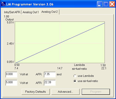
Once LM Programmer is launched click on ‘Analog Out 2’ tab. Next, select the ‘use-air-fuel-ratio’ button. There are four boxes you can modify. The two on the left are voltages and the two on the right are the air/fuel ratios that these voltages correlate to. If you have an LM-1 change your settings to 0V = 7.35 AFR and 5V = 22.39 and click ‘Program.’ If you have the LC-1 these should be your default settings.
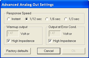
If you click on the ADVANCED button, you can change the Response Speed of the sensor. Too fast of a response speed will cause your air/fuel data log to be sporadic. Too slow of a response speed will be less accurate. You want the fastest speed possible that creates a smooth enough data log to be readable. I would start with “1/12 sec“ and try it. If that‘s too sporadic, try “1/6 sec“. The “Instant” setting is too fast, and causes Live Link to show a jumpy Air/Fuel ratio.
Setting up Live Link
The second piece of software to be installed is SCT’s Live Link. This can be downloaded at http://www.sctflash.com/downloads.php under the name SCT Live Link Data Logging Software. You can set up Live Link to record a number of different parameters. The less parameters you record, the faster they will be updated and the more accurate they will be. The faster the laptop computer is that you are using, the more parameters you can get away with.
For the purpose of this tutorial, I will assume that you are already familiar with how to use Live Link, and are simply looking to add a wideband reading to your data logging capability. If you’re not already familiar, spend a little time getting to know the software before you start tuning your car with it.
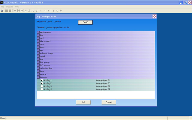
Live Link is capable of logging many different parameters, or PID‘s. I would recommend you log only the parameters in which you are trying to tune at the time. For Air/Fuel ratio tuning, you will probably want to log Inlet Air Temp, Coolant Temp, MAF Counts, Engine Speed, Load, Throttle Position, and the Analog input channel that you are using.
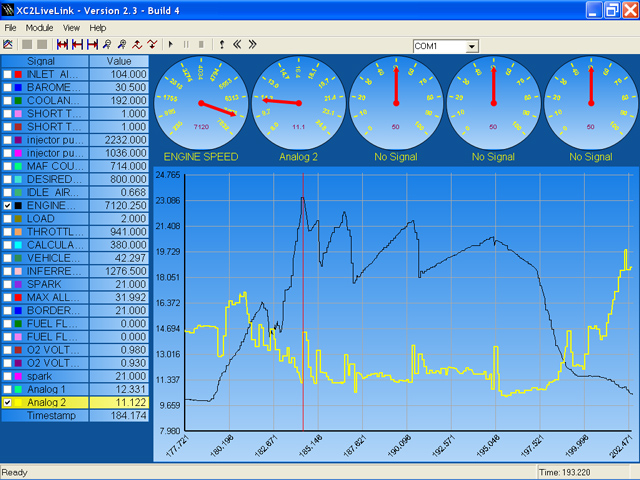
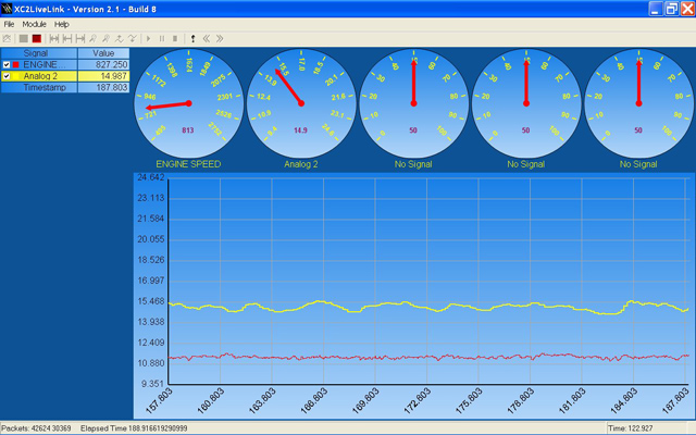
You can set the formula for the Analog input by double-clicking on Analog 2. If you want, you can make the gauges at the top of the screen functional by right clicking on them, and choosing what function they display.
LC-1/LM-1 Integration into SCT’s Xcal 2
written by Steve Hulett
Download a PDF version of this tutorial
This guide will help you connect your LC-1 or LM-1 to SCT’s Xcal 2. It will also show you how to create the wiring, setup the software, and create the formulas for different air/fuel ratio ranges. It is not intended as an installation manual for the Innovate Motorsports equipment, but as a tutorial for interfacing that equipment with the Xcal 2. Please refer to manufacturer’s manuals for details, warnings, and other specific information.
Parts Needed
To set up your data logging system, you will need the following pieces:
- LC-1 or LM-1 unit installed
- 9 Pin Mini-din cable - 6 feet long (or SCT’s cable)
- SCT Xcal 2
- USB A to B standard printer cable (for the Xcal 2 to computer)
- USB to serial DB9 male adapter cable (for laptops without a serial port)
- Notebook computer with USB ports or Serial port

The Innovate Motorsports hardware uses a serial out cable to interface their LC-1 with a laptop computer, via the LM Programmer software. If your laptop does not have a serial port, you will need to acquire a USB to serial DB9 male adapter cable. These may be purchased from Innovate Motorsports or from your local electronics store.
Wiring
Please refer to the appropriate installation manual for specific instructions. I will go over the wiring briefly, because how you wire it will have consequences on overall accuracy that we want to avoid. Specifically, ground offsets. Not all 9 pin mini-din cables have the same color wires, make sure to reference the pin-out diagram below..

LC-1
The red and black wires are explained well enough in the installation manuals. Ground wires are of the most importance here. The ideal ground in a car is always the engine block. To start, ground the Blue heater ground to the engine block. The Green analog ground and White system ground wires can be connected together, and then grounded to the engine block on a lug all by themselves. This is where you will also ground the Xcal2 9 pin mini-din cable’s Analog Ground wire.
We will be using three wires of the 9 pin mini-din cable from SCT. Analog In 1, Analog In 2, and Analog Ground. The blue SCT Analog In 1 wire will connect to the yellow Analog Out 1 wire. The black SCT Analog In 2 wire will connect to the brown Analog Out 2 wire, and the red SCT Analog Ground wire will connect to the ground spot mentioned above, where the Analog Ground and System Ground wires are grounded.

LM-1
The LM-1’s analog output cable has three wires. Red is analog output 1, white is analog output 2, and the remaining wire is the analog ground wire. It is ideal to run the analog ground to the engine block. This is where you will also ground the Xcal2 9 pin mini-din cable’s Analog Ground wire. We’ll talk more about that later, but for now just remember that’s where it’s going to go.
We will be using three wires of the 9 pin mini-din cable from SCT. Analog In 1, Analog In 2, and Analog Ground. The blue SCT Analog In 1 wire will connect to the red Analog Out 1 wire. The black SCT Analog In 2 wire will connect to the white Analog Out 2 wire, and the red SCT Analog Ground wire will connect to the ground spot mentioned above, where the Analog Ground wire was grounded.

Setting up LM Programmer
We’ll be installing two pieces of software on our laptop. The first is the LM Programmer from Innovate Motorsports. This software allows you to program the characteristics of the two analog outputs of the wideband controller. It will be necessary to connected your wideband (LM-1 or LC-1) to the computer and launch LM Programmer for this step.
LM-1
By default, Analog Out 1 is set up to simulate a narrowband oxygen sensor. Analog Out 2 is set up for 1V = 10 AFR and 2V = 20 AFR. We will be reprogramming Analog Output 2 to 0V = 7.35 AFR and 5V = 22.39 AFR (refer to screen shot below).
LC-1
By default, Analog Out 1 is set up to simulate a narrowband oxygen sensor. Analog Out 2 is set up for 0V = 7.35 AFR and 5V = 22.39 AFR. While these outputs are reprogrammable, we will be using the default settings to simplify our installation.

Once LM Programmer is launched click on ‘Analog Out 2’ tab. Next, select the ‘use-air-fuel-ratio’ button. There are four boxes you can modify. The two on the left are voltages and the two on the right are the air/fuel ratios that these voltages correlate to. If you have an LM-1 change your settings to 0V = 7.35 AFR and 5V = 22.39 and click ‘Program.’ If you have the LC-1 these should be your default settings.
If you click on the ADVANCED button, you can change the Response Speed of the sensor. Too fast of a response speed will cause your air/fuel data log to be sporadic. Too slow of a response speed will be less accurate. You want the fastest speed possible that creates a smooth enough data log to be readable. I would start with “1/12 sec“ and try it. If that‘s too sporadic, try “1/6 sec“. The “Instant” setting is too fast, and causes Live Link to show a jumpy Air/Fuel ratio.

Setting up Live Link
The second piece of software to be installed is SCT’s Live Link. This can be downloaded at http://www.sctflash.com/downloads.php under the name SCT Live Link Data Logging Software. You can set up Live Link to record a number of different parameters. The less parameters you record, the faster they will be updated and the more accurate they will be. The faster the laptop computer is that you are using, the more parameters you can get away with.

For the purpose of this tutorial, I will assume that you are already familiar with how to use Live Link, and are simply looking to add a wideband reading to your data logging capability. If you’re not already familiar, spend a little time getting to know the software before you start tuning your car with it.
Live Link is capable of logging many different parameters, or PID‘s. I would recommend you log only the parameters in which you are trying to tune at the time. For Air/Fuel ratio tuning, you will probably want to log Inlet Air Temp, Coolant Temp, MAF Counts, Engine Speed, Load, Throttle Position, and the Analog input channel that you are using.

You can set the formula for the Analog input by double-clicking on Analog 2. If you want, you can make the gauges at the top of the screen functional by right clicking on them, and choosing what function they display.


