Chingon's Engine Build

@XR7-4.6 was the tuning with the cams really crazy?? I tuned my boosted bird but didn’t have to worry about cams in the mix, any pointers?

@Grog6 that’s too much haha we’re lucky the computer does all the work for use.


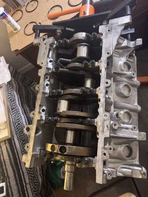
Just installed the accufab 8mm pivot pins into the block, a lil nerve racking trying to get the tap nice and Str8 but honestly it was pretty str8 forward.

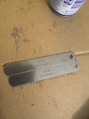
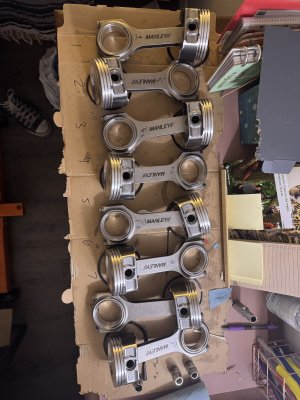
Tomorrow I’m picking up the internals and hopefully assembling the short block, going to set the end gaps to 22 top ring and 26 bottom ring, I’m kinda leaning to 24 bottom but I heard it’s good to have the bottom one bigger.

image.jpg
 
@XR7-4.6 was the tuning with the cams really crazy?? I tuned my boosted bird but didn’t have to worry about cams in the mix, any pointers?


I wouldn’t call it crazy, idle is the issue. Once you’re above idle it’s just normal tuning, not n fact I haven’t changed a thing besides injector delay using the excel file I got from Brandon. But with idle if the cams have a lot of overlap it can be a challenge to keep it from stalling or surging at idle. Unlike WOT tuning the idle tuning can be done with the car parked flicking the throttle blade and datalogging.

The challenge is a wideband and fuel trims from the narrowbands aren’t necessary accurate at those RPMs since there’s so much reversion with both valves partially open so the tack I’ve taken which I don’t necessarily know is the right one is to minimize the ISC (IAC)duty cycle at desired idle to a minimum and open the throttle blade more with the stop screw everyone tells you to never ever mess with. You also want to get the idle integrator to 0 in the logs. This basically removes the IAC from the equation for idle stability and leaves it to fuel/spark.

Right now mine’s just ok. Currently I have it in forced open loop/adaptive off 100% of the time it’s running so the oxygen sensors don’t overcorrect a lean condition that isn’t there due to the overlap(I’ve tried every parameter to get it to go to OL at idle only but I’ve never been able to do it yet), but I still have ways to go and am still figuring it out. I’m probably going to end up raising the idle up from 750 now to 850 or even 900 if I’m desperate next. If it’s still a problem I’ll be hooking up a vacuum gauge and tuning the old fashioned way (albeit without the convenience of a distributor lol)


Interesting, those cams I’m looking at have 114 overlap I think. Which is pretty much stock numbers if I’m correct , since you have NA cams I’m assuming their aver lap is around 110-108??
 
Interesting, those cams I’m looking at have 114 overlap I think. Which is pretty much stock numbers if I’m correct , since you have NA cams I’m assuming their aver lap is around 110-108??

That’s lobe separation angle, though it contributes to overlap. If the intake and exhaust lobe durations are low enough you could have zero overlap regardless of LSA, (which is basically factory cams).

On 4 cam engines you can set the LSA to whatever you want, mine’s 112.5 degrees. With 230° duration on both cams and that LSA the overlap is about 5°
 
@XR7-4.6 there we go that’s what I meant. I think stock PI cams are in the 116 range, so those stage 2 shouldn’t be too far off. Did you do the pivot pins on your engine?
 
@XR7-4.6 there we go that’s what I meant. I think stock PI cams are in the 116 range, so those stage 2 shouldn’t be too far off. Did you do the pivot pins on your engine?

Nah, from what I’ve read over the years those aren’t necessary to upgrade until you run heavier valve springs or are running way higher RPM than I am. My cams have a lot of duration but they aren’t high enough lift to necessitate upgrading either.

And yeah I believe 116 LSA is stock for both 2V and 4V, which is more emissions friendly
 
Before I start, are these the 2 gauges I’m using for the rings?

Going with 22 top and 26 bottom
 

Attachments

  • image.jpg
    image.jpg
    1.6 MB · Views: 12
Last edited:
Before I start, are these the 2 gauges I’m using for the rings?

Going with 22 top and 26 bottom

Yes, main thing to make sure is have the rings evenly set in the cylinders when you measure them, which you can do using a piston with a ring installed in the second groove to stop it to evenly push down the ring being measured/gapped into the cylinder.
 
Torqued the crank down today

Tomorrow I’m assembling the rods and hopefully getting the short block put together.
 

Attachments

  • IMG_9506.jpeg
    IMG_9506.jpeg
    2.5 MB · Views: 9
Put the pistons on the rods today, rings are going in tomorrow and hopefully that’s a wrap on the short block. Those little rings that hold the pin in place, what a bitch haha. One flew out and almost hit my eye, after 2 sets it went by pretty fast tho.

Also, I’m putting the oil pump and it seems like it SUUPPERR tight in the crank, is there some sort of shimming I need to do or just throw it in and tighten down?image.jpg


Also also I ended up picking up those “stage 2” comp cams for $300 off FB marketplace. Brand spanking new still in the bag. Do I need a new cam bolt or can I reuse my old ones? They are going to be installed Str8 up

IMG_9518.jpegIMG_9519.jpeg
 

Attachments

  • IMG_9515.jpeg
    IMG_9515.jpeg
    3.2 MB · Views: 4
That pump housing to crank clearance doesn’t look good, where’d you buy the pump? There are ALOT of Melling counterfeits flooding the market and that’s giving me concerns

 
That pump housing to crank clearance doesn’t look good, where’d you buy the pump? There are ALOT of Melling counterfeits flooding the market and that’s giving me concerns


I see, this one came from rock auto, so It should be legit. The box is also the smaller of the 2 from that video you posted.

That clearance is very concerning, its almost riding on the crank. Tomorrow I’m thinking of grinding down a lil bit on all those tabs to get that clearance back.
 
I see, this one came from rock auto, so It should be legit. The box is also the smaller of the 2 from that video you posted.

That clearance is very concerning, its almost riding on the crank. Tomorrow I’m thinking of grinding down a lil bit on all those tabs to get that clearance back.

I’d actually be inclined to contact Melling directly and see what they have to say. If it’s fitting that snug to the crank it makes me think Rockauto bought into a batch of “too good to be true” pumps themselves or it’s defective. The video is two years old so it’s to be presumed the counterfeiters have caught up on some of the tells by now.

Maybe I’m just being paranoid or pessimistic. I went through this last year myself and ended up buying a pump directly from Tasca Ford. Cost me $50 more than a Melling but it’s without question legit. I’ve spun rod bearings two too many times to introduce a questionable oil pump to the mix
 
@XR7-4.6 i think your right, I’m gonna call them tomorrow in the morning. I’d rather not trash this engine simply due to this pump chewing up the snout of the crank. Thanks for the advice!
 
Got a this mark 8 pan for $40 today with the pick up. Need to clean the inside tho, any tips?


IMG_9538.jpeg
 
Thanks for the tip, I check inside and it seems like the oil isn’t too dirty or any metal flakes.

Also, i got this block with a broken stud in it, I tried extracting it and BROKE the extractor inside aswell 😅. That piece is so hard, purchased a cobalt tipped drill bit set and it wouldn’t even scratch it, would the next step be a carbide bit or just drill and tap another hole adjacent to this and call it good enough?


IMG_9540.jpeg
 
Thanks for the tip, I check inside and it seems like the oil isn’t too dirty or any metal flakes.

Also, i got this block with a broken stud in it, I tried extracting it and BROKE the extractor inside aswell 😅. That piece is so hard, purchased a cobalt tipped drill bit set and it wouldn’t even scratch it, would the next step be a carbide bit or just drill and tap another hole adjacent to this and call it good enough?


View attachment 16197
It needs a nut welded to it. That introduces a lot of localized heat and gives you something to wrench on. My only reservation in suggesting it is the bolt looks countersunk.
 
It needs a nut welded to it. That introduces a lot of localized heat and gives you something to wrench on. My only reservation in suggesting it is the bolt looks countersunk.
its about 1/8 in the hole, unfortunately I don’t have a welder on hand to do that. It’s hardened metal, the extractor bit and incredibly hard to dril through. I’m hoping a carbide bit will cut though it.

Just my luck 😂
 
If welding isn’t an option I’d get a left hand drill bit. Even if it doesn’t drill through the bolt the torque applied is going the right direction.

Don’t drill an adjacent hole. I’d recommend just leaving it out to that option
 
I’ll give that a try thank you! Going to hit Home Depot and return those weak ass cobalt bits. If that doesn’t work I might literally buy a c clamp or pliers and just clamp it shut 🧐
 
Liberated the cylinder heads today, remind me never to do this again with the engine in the car 😭


IMG_9560.jpeg


Taking the heads today to get hot tanked, hopefully that cleans the inside from all metal glitter.

Unfortunately the cam caps looke a little scorn but after some reading, they should clean up with some scotch Brite or 1000 Brite sand paper.


IMG_9562.jpeg
 
Got the felpro 70415 gasket at the auto parts. It’s for the Romeo block and just wondering if I’ll have any leak problems from using it?? I’ve read theres 2 sizes to pick from, anybody come across this?

Teksid block and Romeo oil cooler.


IMG_9610.jpegIMG_9611.jpeg


I also measured the space from pan to pick up and it seems like I have 3/8” gap between both which I read was optimal. Obviously I suck as math 😬 so I sent the measurements to my engineer buddy who works for rocket lab and that’s what he told me

Pretty much oil pan depth 5 1/8
Oil pick up height 4 3/4

That gap should be 3/8”?
 
Last edited:
How thick is your gasket. With no gasket you are at 3/8. If its a good steel core rubber gasket you'll add another 1/8". I would get it that 1/8" closer so you stay at 3/8" or less
 
How thick is your gasket. With no gasket you are at 3/8. If its a good steel core rubber gasket you'll add another 1/8". I would get it that 1/8" closer so you stay at 3/8" or less

That measurement is WITH the FEL-PRO 30725 on the mating surface of the engine block. It’s a plastic gasket.
 
The gasket looks ok to me, the coolant port shape is the difference between blocks but it’s pretty obvious, as long as the back side of the gasket is on a machined surface you should be fine IMO
 
Back
Top