How do you troubleshoot the IRCM?

GRWeldon

5th Gear Poster
Joined
Oct 5, 2023
Messages
440
Location
Alabama
Country flag
On my 94 SC... My cooling fan isn't coming on, my push fan nor my AC fan on the inside are working. I suspect that the Integrated Relay Conrol Module is faulty.

Are the symptom I described classic symptoms of a dead IRCM? If not, i really would like to know it's faulty before I buy a working unit for over $100. I'm pretty much wiring diagram illiterate but might be able to follow a step-by-step procedure...

I have several parts cars but the part number for the SC (F48F-12B577-BA) isn't the same as a 94 NA 3.8 nor a 96-97 4.6. Anybody know if one from another engine would work regardless of the part number, maybe at least for a test?

And as a last resort, if it is determined that my IRCM is indeed faulty, can it be fixed easily? I can desolder/solder components...

Thanks All!
 
I don't like going to computer components without checking some other stuff first. Like on the cooling fan, it's supposed to get voltage something like when the coolant temperature gets to 204 or when the a/c is on? Not a big fan of tracing wires either, but I think I'd try to check the signal into and out of the computer before changing it. Of course use a digital multimeter with at least 100 mega-ohms of impedance, most of them even the cheap ones do these days.
 
I don't like going to computer components without checking some other stuff first. Like on the cooling fan, it's supposed to get voltage something like when the coolant temperature gets to 204 or when the a/c is on? Not a big fan of tracing wires either, but I think I'd try to check the signal into and out of the computer before changing it. Of course use a digital multimeter with at least 100 mega-ohms of impedance, most of them even the cheap ones do these days.
Thanks Jim for the reply. I sincerely appreciate the time you have taken to reply. Remember, I'm electronics illiterate. I'm not sure what you mean by checking "signal" into and out of the computer. I'm not sure the IRCM can be considered a computer. I believe it's just a box containing 3 or 4 relays that control different things. I suppose the PCM (THE computer) controls the IRCM somehow but I'm not sure what I would be checking or what values I should expect to find...

Please elaborate if you can...
 
My cooling fan isn't coming on, my push fan nor my AC fan on the inside are working. I suspect that the Integrated Relay Conrol Module is faulty.
Does your A/C compressor engage when you turn on the A/C? I don't believe the cooling fans will engage unless the A/C compressor engages. When you say "fan on the inside" are you referring to the engine cooling puller fan or the HVAC blower motor in the passenger compartment? Do you have a way to know what engine temperature the EEC is seeing?

This is for a Turbo Coupe, but there is some good information here. If you follow the links he gets into taking it apart. Looks like just regular relays soldered to the board inside. I think they are definitely repairable.

I hate electrical diagnostics as much as you.
 
If you put the PCM into KOEO mode it will run a self test on the IRCM automatically - fuel pump, low and high speed fans ..
 
Sorry, I'm getting into wiring diagram stuff but trying to be general. And I'm too lazy to actually look up anything. So when commanded to come on by operating conditions like coolant temp or a/c turned on, voltage should go to the cooling fan. If it doesn't it's either the wiring, whatever is supposed to be sending the voltage (I don't know if that would be the IRCM or the PCM), or whatever electronic component receives the input signal, like from the coolant temperature sensor. In the case of the cooling fan, I'd be more suspicious of the coolant temperature sensor than the IRCM (if not the ground to the fan or the fan motor itself). If it's the IRCM, have to wonder, what caused it to fail and do conditions still exist to cause a replacement to fail?
 
Does your A/C compressor engage when you turn on the A/C? I don't believe the cooling fans will engage unless the A/C compressor engages. When you say "fan on the inside" are you referring to the engine cooling puller fan or the HVAC blower motor in the passenger compartment? Do you have a way to know what engine temperature the EEC is seeing?

This is for a Turbo Coupe, but there is some good information here. If you follow the links he gets into taking it apart. Looks like just regular relays soldered to the board inside. I think they are definitely repairable.

I hate electrical diagnostics as much as you.
Thsnks for the reply! The AC compressor doesn't come on because the system isn't charged. The HVAC fan Interior blower motor) does not come on. It should even if the system isn't charged to provide heat in cooler weather.

The cooling fan does not come on at all, either when the car goes above normal temp. or when the AC is turned on.

I have an OBD II scanner but all SCs are OBD I. I can't read what the EEC is getting for temp.
 
Any box in the car is going to require an evtm for that year to troubleshoot. Any electrical or vacuum problem, really.
most boxes will work if you provide power and ground, and pulse the input side with the appropriate voltage, and seeing if the corresponding output side switches.
If you're not willing to spend the time to troubleshoot your car, you're out of luck. The eec feeds the input side;idk if that's 5V or 12V signals, you'll need a voltmeter to see. If you put 12V on a 5V input, you'll have a dead box.
 
If you put the PCM into KOEO mode it will run a self test on the IRCM automatically - fuel pump, low and high speed fans ..
I'll try to figure out how to do that. I've read something about it in the past. Thanks.
 
Any box in the car is going to require an evtm for that year to troubleshoot. Any electrical or vacuum problem, really.
most boxes will work if you provide power and ground, and pulse the input side with the appropriate voltage, and seeing if the corresponding output side switches.
If you're not willing to spend the time to troubleshoot your car, you're out of luck. The eec feeds the input side;idk if that's 5V or 12V signals, you'll need a voltmeter to see. If you put 12V on a 5V input, you'll have a dead box.
It's not that I'm not willing to put in the time, I just don't quite understand the diagrams. Even if I did I don't think I have the right equipment to apply voltages and whatever else I need to do. Basically I lack electronic troubleshooting education. I'm trying to grasp things in the chunks here and there that y'all post but it's a far cry to proper education.

I can tell you how most things on the car are made because of my background as a machinist, toolmaker/designer and manufacturing engineer. Unfortunately, the electronic side of things is a completely different career path...

I need some hand holding to begin. I can understand nobody wanting to give it. I may eventually stumble upon something that leads me to the issue...maybe not, but at this point all I can do is ask questions and hope somebody here can answer directly and lead me where I need to go.

I appreciate all everybody does, especially for the price, but it's not like I can depend on regular answers to all my questions, I understand that, and it shouldn't be any other way. Y'all have helped me a lot in many things, but not everything.

Again, if you tell a guy who has never been educated in construction methods to go build a house, he's going to look at you dumbfounded and not have a clue where to start. If he's got ant kind of grit he'll start asking a bunch of questions to try to understand how to begin. That's where I'm at right now. Some people know how to troubleshoot electronics with hardly any experience or education in the matter. Unfortunately that's not me.
 
The eec feeds the input side;idk if that's 5V or 12V signals, you'll need a voltmeter to see.

The EEC provides a ground circuit to trigger the relays.

I'll try to figure out how to do that. I've read something about it in the past. Thanks.

Screenshot_20240818_130123_Chrome.jpg

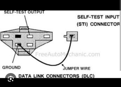
Simple .. use a jumper wire as shown in the diagram. When you turn your key to the Run position ( KOEO .. Key On Engine Off); you will hear some relays click, fuel pump prime, low speed fan and high speed fan should run - then it will start blinking the CEL if any error codes exist. This is how you self test the IRCM and pull codes without a code reader.
 
Last edited:
The EEC provides a ground circuit to trigger the relays.
That makes it harder to hurt the module.
In most electronics, its easier to drive a ground efficiently, most high-side drivers are actual relays.
So, probing the inputs with a ground wire should activate the circuit. It really doesn't get much easier than that.
 
That's what I was getting at; an electronic 'low side' driver is a npn transistor. It won't give a fuck about jumping an output wire to ground. If it's on, and you jumper it to 12V, It won't work after that. I recommend a 1A fuse with leads on it as a probe. seeing it blow when you probe the wrong spot keeps you awake,lol.

If all tis is foreign to you, start here, OP:https://learn.sparkfun.com/tutorials/how-to-use-a-multimeter/measuring-voltage
 
Last edited:
That makes it harder to hurt the module.
In most electronics, its easier to drive a ground efficiently, most high-side drivers are actual relays.
So, probing the inputs with a ground wire should activate the circuit. It really doesn't get much easier than that.
Grog...you are talking over my head. I understood what dDUBb said in the message before yours. Your message probably makes sense to an electronics guy. It might as well be Russian to me... But thanks for posting. You might be able to get down to my level someday...
 
The EEC provides a ground circuit to trigger the relays.

Simple .. use a jumper wire as shown in the diagram. When you turn your key to the Run position ( KOEO .. Key On Engine Off); you will hear some relays click, fuel pump prime, low speed fan and high speed fan should run - then it will start blinking the CEL if any error codes exist. This is how you self test the IRCM and pull codes without a code reader.

Thanks man. I'll try this as soon as it stops raining...
 
I had trouble a while back because car had sat for some years and I found it is often corrosion in the elec fan connector. I unwrapped the leads from fan back to the solder joint just before the ccrm box. Unless there is wiring damage I would go to harbor freight and get a $12 set of backprobes to plug into connectors to test for voltage when a/c is turned on. Cooling fan automatically comes on when a/c is on provided a/c works. If pressure is too low from leaking refrigerant then it might not trigger. I have like 3-4 boxes and one I opened up to look at. It is stupid to place 3 cubes on a small board and rivet it shut. You could always use schematics to intercept signal from ecm and connect to control side of a stand alone relay connecter and let that run fan IF necessary. My experience has been motor burnt so sniff and see if it smells like electric fire.
 
I had trouble a while back because car had sat for some years and I found it is often corrosion in the elec fan connector. I unwrapped the leads from fan back to the solder joint just before the ccrm box. Unless there is wiring damage I would go to harbor freight and get a $12 set of backprobes to plug into connectors to test for voltage when a/c is turned on. Cooling fan automatically comes on when a/c is on provided a/c works. If pressure is too low from leaking refrigerant then it might not trigger. I have like 3-4 boxes and one I opened up to look at. It is stupid to place 3 cubes on a small board and rivet it shut. You could always use schematics to intercept signal from ecm and connect to control side of a stand alone relay connecter and let that run fan IF necessary. My experience has been motor burnt so sniff and see if it smells like electric fire.
Thanks for the reply. After some family issues have passed and recreational things completed (I'm an N-scale modular railroad modeler) I'm back on this project. Unfortunately, the AC does not work.

I'll add checking for corrosion on the fan leads to the list...
 
The EEC provides a ground circuit to trigger the relays.


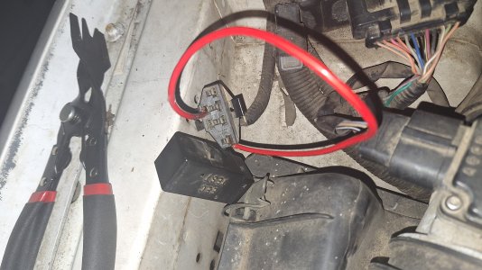
View attachment 7157

Simple .. use a jumper wire as shown in the diagram. When you turn your key to the Run position ( KOEO .. Key On Engine Off); you will hear some relays click, fuel pump prime, low speed fan and high speed fan should run - then it will start blinking the CEL if any error codes exist. This is how you self test the IRCM and pull codes without a code reader.
After following this procedure, the only thing I get is a repeating airbag light flashing 51 until I turn off the ignition. We've discussed this intensely in another thread where one of the regulars (possibly you) provided me with the diagram for the airbag system. I'm tempted just to replace the airbag control module because I'm lazy and doing due diligence for the "easy" things hasn't turned up anything. Of course if it blows again I guess I'll be under the dash up to my elbows in wires.

I suppose I'll remove the dash because with the sad shape my shoulders are in I won't be able to sleep at night because of pain. Removing the dash might make the process easier. I wonder how much shit I'll break when I do THAT!
 

Attachments

  • 20240926_160331.jpg
    20240926_160331.jpg
    3.5 MB · Views: 1
Sorry, I’m late to the discussion and honestly don’t have time to read through all that’s been discussed so far, so forgive me if this has been mentioned, but wanted to ask how old is the fan? Have you considered replacing it. Good contacts and all other things considered are pointless if the fan motor itself is bad or going bad. I replaced mine a few years ago. It was one of the last original parts in my engine bay.
 
Sorry, I’m late to the discussion and honestly don’t have time to read through all that’s been discussed so far, so forgive me if this has been mentioned, but wanted to ask how old is the fan? Have you considered replacing it. Good contacts and all other things considered are pointless if the fan motor itself is bad or going bad. I replaced mine a few years ago. It was one of the last original parts in my engine bay.
Thanks for the reply. I'm sure the fan is original, but it works well wen 12V is applied directly...
 
Click on the envelope icon next to your username at the top of the screen, select "Start a New Conversation" Type "Rodeo Joe" in the Recipients line. (It Should auto-populate) and hit enter.

Proceed to type your message and then click "Start Conversation" at the bottom.
 
No flaming. When I replaced the starter on the 4.6 it only had two holding it in. It had apparently been like that for at least 5 years before I got to it. I know most people leave that third bolt out.
 
That third bolt doesn’t do jack.


Here’s how unnecessary it is. I have a 5 speed, and I sometimes leave it in first if I’m parked on a hill *just in case* the parking brake cables randomly failed, and of course I forget and momentarily start it in gear/parking brake on with the reddest of cheeks after the most hideous of sounds/sensations, and my starter with its two accessible bolts only is just fine, as is the block.

It’s a stupid example of my clumsyness but it’s a pretty good test for two bolts vs 3
 
So let me get this straight. To test the CCRM apply fused (1 A or less for CYA) to power pin and just ground the other Inputs to check functionality? I have the EVTMs so that's not an issue.

One of the many other issues I'm dealing with since recovering the SC. The hack electrical work has been the most frustrating.
 

Similar threads

Back
Top