Corrected an unforeseen snag today; so to recap going way back to my DOHC swap I did the steering shaft mod to clear Mustang exhaust manifolds, using extra aftermarket U joints, shaft sections and a custom firewall mount for a support bearing. Simultaneously I also swapped in a 03 Cobra rack with a unisteer U joint as it uses a triangle coupler rather than the stock rack’s 36 spline coupler. This all worked very well though it was a bit rupe golbergian and had zero collapsibility (I tend not to sweat safety but that always bothered me a little).
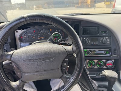
Fast forward to now, with the install of Kooks headers I was able to restore the factory steering shaft and get rid of the mod setup, but what remains obviously is the Cobra rack and unisteer U joint, and hooking it up to the stock shaft/column resulted in the steering wheel turned left with the tires straight, or the tires pointed right with the wheel straight…”huh” …. Actually if you go back and treat yourself to the open header video you can see this issue as I discovered it… Ok no biggie, just adjust the tie rods right? Wrong! It took 11 turns per side to get the steering wheel centered which resulted in the left tie rod being right on the edge of adjustment…
View attachment 13189
So what’s up? Well have a look at the end of our stock steering shaft, it’s typical 3/4 DD shaft(other than the breakaway) but the column u joint attachment randomly veers… you guessed it counterclockwise to the left, exactly where it put my steering wheel.
View attachment 13195
Even though Mustangs use the same column we do their steering shafts don’t have that twist, they’re just clocked differently. An idiosyncrasy that hadn’t/wouldn’t have occurred to me making a custom steering shaft from scratch.
View attachment 13196
The solution then is pretty simple, replace it with straight DD shaft, right? Wrong! Though the sleeve section of the shaft would gladly accept universal DD shaft, it’s not a perfect fit, there’s slop to it, which you’d absolutely be able to feel through the wheel, the way Ford mitigated this was embossing these nylon pads into the portion of shaft that goes inside the sleeve, taking up all the slop.
View attachment 13197
(The one at the end is mangled as I had modified it for mock-up purposes)
Sooooo… what am I to do, you ask? Well as I said the stock shaft is just DD shaft, I can just lop off the end section and move the U joint into that. Mind you it does veer wildly at the breakaway but there is enough straight section (about 5/16”) before it curves into it, but that’s not enough, what I did was utilize the full 3/4” round stop and blend it right into the DD shape in front of it. Worked like a charm!
View attachment 13190View attachment 13191View attachment 13192View attachment 13193
Steering wheel now turned pretty much exactly the same amount right as it was left before, but this time I’ll have plenty of inner tie rod to correct for it(I bet it’ll be exactly 11 turns per side)
View attachment 13194


") . Not sure of other makes, but a lot of later model Lexus and Toyotas use the ABS pump to supply brake power assist. On the rears you just loosen the bleed screw and the pump pushes fluid through. I was doing a '21 4Runner a couple of months ago and forgot about that. It wasn't until the end that I realized they still used the same system I had first seen on an '04 Lexus.
. Not sure of other makes, but a lot of later model Lexus and Toyotas use the ABS pump to supply brake power assist. On the rears you just loosen the bleed screw and the pump pushes fluid through. I was doing a '21 4Runner a couple of months ago and forgot about that. It wasn't until the end that I realized they still used the same system I had first seen on an '04 Lexus.


")


 Are you gonna do the A pillar mount?? I didn’t go that route because it’s kind of a burn; going for a bit of the sleeper look.