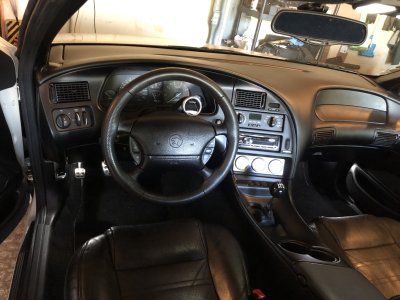
XR7-4.6’s disjointed build thread 2 Electric Boogaloo

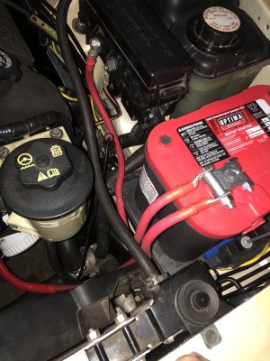
Didn't I send you that battery tray...over a year ago?

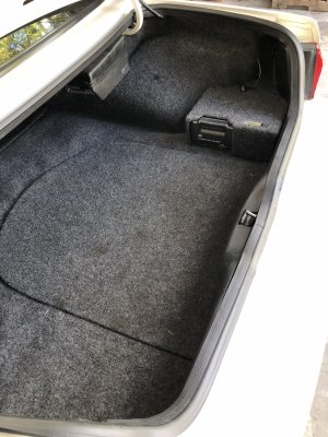
Fun fact: my roommate's Cadillac ATS comes stock with the battery in the trunk. One time, he disconnected it to clear a code which my app refused to clear for some reason; and then he closed the trunk! And there's no way in without power; base ATS without folding seats. We had to use jumper cables on the terminals under the hood just to open the trunk.

It's great that you could repurpose that firewall passage. I had the same luck: the original owner had a cable-operated supplemental hood latch, but the key was missing. I used that passage for cornering light/DRLs.

Probably, as you can see this wasn’t a hasty plan 😆

This is actually technically the third repurposing of that hole as it from the factory was the ABS sensor wire passthrough…. Which I also deleted… but before I deleted ABS entirely I rerouted all the ABS wiring through the PCM harness on the passenger side to clean up the firewall, which conveniently gave me a spot for the battery cable to go when that came to fruition.

The Cadillac situation is how it is in my mom’s Prius V. The starting battery went dead on it and in order to open the tailgate to get to it you have to jumper the leads in the engine compartment.
 
Is it true that only the factory cd player had those controls? You'd need one of those to figure out the communication protocol, but a "bus pirate" would do it. Then a pic controller to do the actual talking to the changer.
But, a 256gb usb drive holds 10x what the changer does. Doesn't your Alpine do FLAC?

Actually only the factory cassette deck has the changer controls. The changer harness physically plugs into the factory CD player but it doesn’t have the circuitry to control it.

All my music is digital now, I just listen to it off my phone with Bluetooth
 
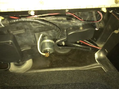
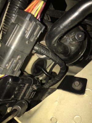
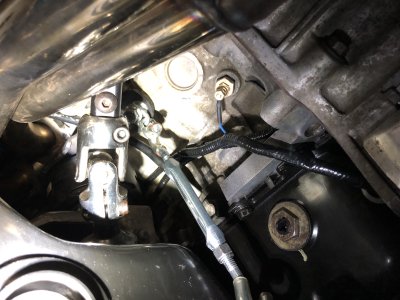
Anyway this took forever. The damn cable bracket on the passenger side sure is a lot easier to access with the K member dropped lol

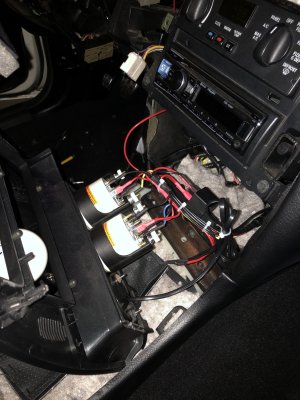
IMG_7448.jpegIMG_7449.jpegIMG_7452.jpeg

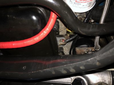
I did get the oil pressure sender in at least. The only thing accomplished directly related to the main project 🙃

IMG_7455.jpeg
 
Last edited:
Most of these pictures kind of suck but I’m beat and you can tell what’s going on in them

Starting from the… start….

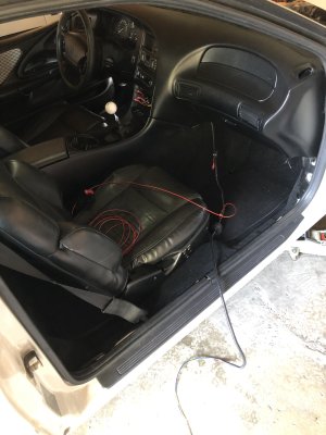
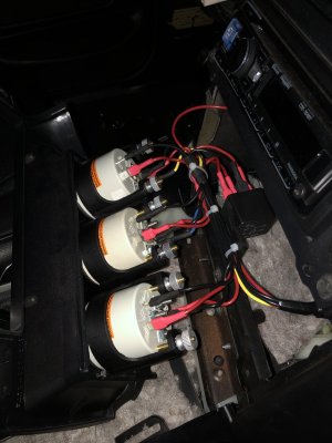
Gauge harness going in!

IMG_7457.jpeg

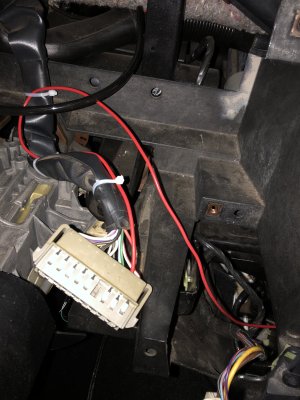
That red wire coiled on the seat is a last minute addition, I had forgotten I powered the stock JBL sub amp from a wire directly off the battery and in searching for a hot at all times wire in the trunk area to no avail(closest is the RKE which I didn’t want to use) so I ended up running it into the gauge harness.

IMG_7466.jpeg

I haven’t tucked away the zeitronix wires yet but it helps to see how they’re run. I’m very happy with how it turned out under here, I kind of guessed where things key things would end up and they ended up exactly where I wanted

IMG_7464.jpeg

Such as that passthrough location. Literally follows the same path as the battery cable did, through the hole in the apron and under the frame rail… actually this one I used the close hole the fuel lines used since my harness had more flexibility than the single cable. I like this routing better

IMG_7458.jpegIMG_7472.jpeg

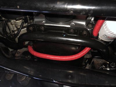
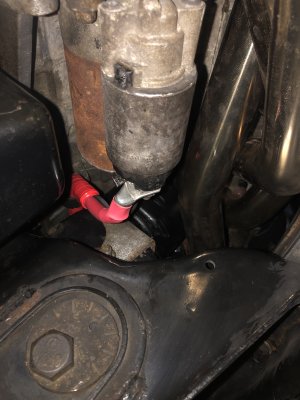
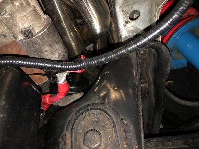
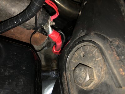
Once again following the path of the old battery cable from the cabin, the harness runs under the frame rail and directly to the starter B+ terminal. You can also see I managed to squeeze my hand through the k member/starter/oil pain tumor trap without getting stuck to run the ground wire to the block.

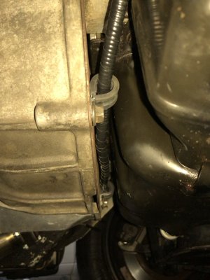
From there I took a path I didn’t intend to take but it turned out to be vastly easier than following the battery cable under the pan as I first planned

IMG_7459.jpeg

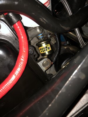
And from there I simply ran the wires to the senders

IMG_7460.jpegIMG_7463.jpeg


The coolant sender was fun to put in, didn’t want to drain the new coolant in spite of it literally going in place of the block drain, but I managed to get it swapped with only a little bit of an antifreeze shower 😆


Still not done! I have a few ideas on what to do with the cluster gauges that will no longer function with these in their senders place (or will they???)
 
If you're going to run both, make sure the reading doesn't change when you add the cluster ones. I don't think it will work accurately.
 
If you're going to run both, make sure the reading doesn't change when you add the cluster ones. I don't think it will work accurately.

I’m not intending to run them off the autometer senders, I’m going to try something completely different
 
Alright so I mentioned I had plans for the factory cluster temp and oil gauges now that the autometer senders have stolen their places… well here’s the half satisfying result…
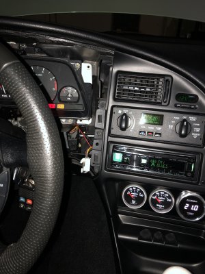
IMG_7487.jpeg


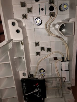
Looks like I demodded the oil gauge to function like stock pointing toward the middle right? Well I kinda did. But notice the engine is not running! Did I cheat and simply snip the resistor jumper and run the connector to ground?


Nope I did something ludicrously complicated, making what was from the factory effectively a dummy light shaped like a gauge a DIFFERENT dummy light shaped like a gauge…
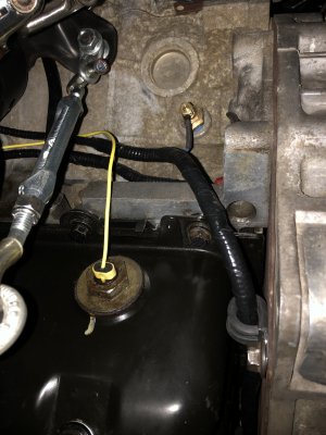
IMG_7488.jpeg

The heretofore unused oil level switch on my mark pan! Hey the gauge just says OIL, it doesn’t explicitly say pressure! 😆

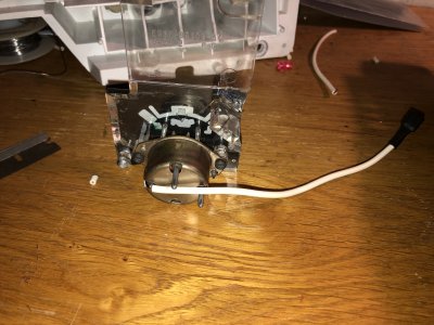
So simple enough right? Well… there’s a problem or several. First off the factory “analog” oil pressure switch is a normally open switch… eg you have no oil pressure the gauge reads 0 and the switch it open you’re having a bad time. You have oil pressure the switch closes gives a path to ground and your “gauge” points to the middle and you feel all warm and fuzzy 👍

Digital gauges, or clusters with dummy lights(97) are the opposite with normally closed switches so the circuit grounds with low to now oil pressure to illuminate the light, with proper oil pressure it opens to turn it off.

Why am I explaining how these work? Because the level switch works the same way as the latter - low oil LEVEL the switch is closed and the message center will tell you to “fill your oil, dummy!”….which means plugging it in directly to the gauge works the opposite of how I want. Damn…

But then I had a vision, a vision of this!
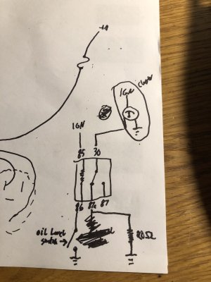
IMG_7490.jpeg

This is what makes oil level sensing through an analog gauge possible!

So here’s what I whipped up
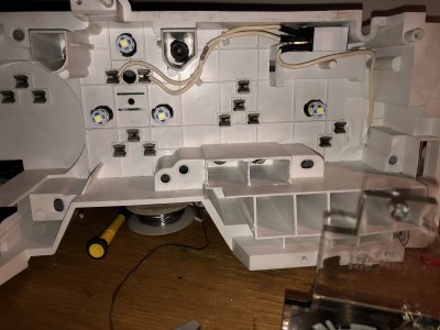
IMG_7482.jpegIMG_7483.jpegIMG_7485.jpegIMG_7486.jpeg

My expertly drafted diagram basically explains it. I actually made a mistake initially deleting the resistor jumper but in this circuit I need both a full current circuit the jumper originally in place for the pressure sender provided, but ALSO the resistor itself but in a different place in my added wiring to ground through the volt gauge - terminal.

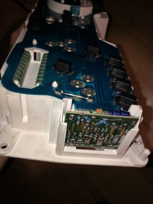
The other thing is the modification to my slosh module… I actually forgot what exactly I did here because I did it years ago to stop the check gauges light from triggering from the oil sender but it is necessary for this mod as well since it’s expecting to see voltage through the signal circuit when running, which it isn’t.

Anyway, here is a quick clip in action with me manually shorting it to ground(you can hear the relay click)


The only sucky part is I had kind of hoped the oil temperature sensor part of the mark VIII switch would work for the temperature gauge(it once again doesn’t say *which* temperature! 😆) but it ohms our way way higher than the gauge sender unfortunately, closer to the ECT sensor.
 
Last edited:
You could use a npn transistor and a couple of resistors. I'm interested; the 6qt pan I bought from Oscar has that sensor. Got a pinout?
 
You could use a npn transistor and a couple of resistors. I'm interested; the 6qt pan I bought from Oscar has that sensor. Got a pinout?
The outer two wires are the temperature wires(signal and signal return(which for a gauge can be ground). The middle is the level sender which grounds through the pan through the block etc.

Show me the way and I’ll follow! The stock sender at ambient temperature(bout 70° last few days) is about 200ohms and the oil temperature sensor was about 24k ohms
 
You have any electronic parts? A 2n2222 transistor, a 10k resistor,a 330 ohm resistor, and a 10k pot will get you there.
I'll dig out my pan tomorrow;I need to drill some rivets, and see if my battery will charge. If it will work like I think, I can probably throw those parts in an envelope.
 
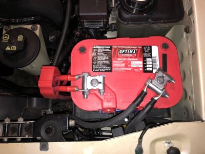
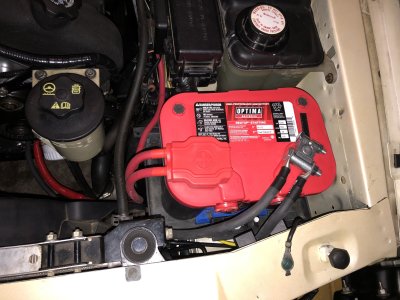
Battery re-relocation officially done! I needed more 1/0 lugs for the ground cables and there was a shipping debacle with them but they arrived today and I got it done tonight! Sure its not as clean as in the trunk, but it’s neat looking to my standards. 🙂

IMG_7584.jpegIMG_7581.jpegIMG_7582.jpeg

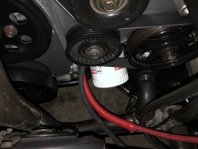
So in summary, the positive cable is a reuse of the Lincoln LS cable I had previously used which happens to be 1/0 gauge, the ground cable is 1/0 welding cable, the lugs are 1/0 5/16 tinned lugs (I embiggened the terminal ends to 3/8”), the ground cable grounds to the block via the PS pump mount boss… which is conveniently unused in my case as the pump is mounted to the head allowing for the ultimate oil filter relocation 😝 the terminals are MIL spec type, and while I could have used common as dirt marine ones these simplylooked cooler to me!

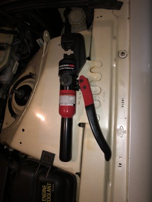
Btw this Harbor Freight crimper kicks ass.

IMG_7586.jpeg
 
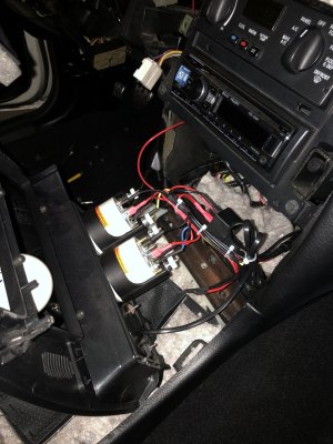
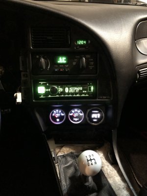
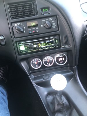
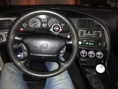
Well true to form I got tired of the gauge pod looking like the emperor’s eyes from the pre-special edition version of Empire Strikes Back…

1758329275352.jpeg

IMG_7599.jpeg

See it? I sure do lol

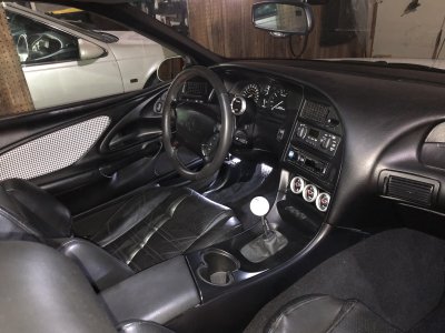
So…… I knew this was inevitable so I prewired it for another autometer.
IMG_7475.jpeg

IMG_7623.jpeg

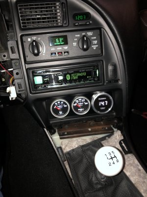
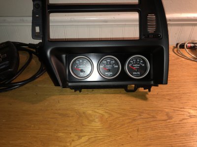
Nothing fancy, just a volts gauge like the usual day two muscle car gauge 3 pod. I also redid the bezel for the third time as the spacing was way off on the middle gauge…. And still kind of is, damnit lol but I did a much much better job this time, I even bought a new hole saw that’s actually bimetal!

IMG_7621.jpeg

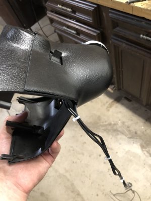
So what of the wideband gauge which was the first gauge that I bought, that made me want more gauges, that turned that $100 purchase into a $500 project? Well I’m going back to putting it in the column shroud I kind of hated lol

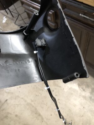
So first of all I refinished it in the same paint as the rest of the interior is so it matches the column better, second I actually used double sided tape to hold it to the stock shroud better, and clearanced the hole for the hazard button which was way way too tight out of the box.

The other thing that bothered me was the shroud is universal fit, in that it has a cutout for the manual trans key release, which I don’t have or want in spite of having a manual trans… so what to do with the hole… well part of what I don’t like about the WB gauge there is at night it’s really really bright, and there’s no way to dim it, but I can shut it off! So that’s what I did, I added a switch that somewhat resembles the key release I can toggle the wideband on and off making that useless hole in the shroud actually fairly useful.

IMG_7626.jpegIMG_7627.jpeg

And back together. I like it better already, very street machiney, I just need a foot shaped accelerator pedal lol

IMG_7631.jpegIMG_7632.jpeg

Oh yeah I also swapped in a SC cluster and plumbed in the vacuum/boost gauge into my NA car:innocent:
 
Last edited:
I like that a lot. That is one thing I don't like about AFR gauges. Somebody needs to make a needle sweep version.

From that last picture for a second, I thought you got another pearl MN12.
 
I like that a lot. That is one thing I don't like about AFR gauges. Somebody needs to make a needle sweep version.

From that last picture for a second, I thought you got another pearl MN12.

Autometer makes needle sweep widebands but they’re very expensive, at least twice more than my zeitronix setup including the gauge.


I’d been curious about adaptability mixing gauges and controllers but from what I’ve found because of voltage ranges they all vary (zeitronix should use zeitronix, AEM should be AEM etc), plus some seem more accurate/reliable than others with limited functionality.
 
So the SC boost gauge really works? I’m assuming it only read vacuum??
 
I feed the analog output of my aem to the port on the xcal2, and add it as an analog gage in livelink.
 
That's a lot of money for a gauge. I prefer the luxury of not knowing.

Tell me about it lol I hooked it up after the cams/headers/exhaust redo to see what’s going on and it turned out a lot! I wanted a real time way to see what was happening without hooking up my 10 year old laptop.

So the SC boost gauge really works? I’m assuming it only read vacuum??

Yeah vacuum is what I wanted to see since I’m in the tuning phase of things. Since I have a volts gauge elsewhere now I may as well use this lol

I feed the analog output of my aem to the port on the xcal2, and add it as an analog gage in livelink.

So do I with the zeitronix(I never used the gauge itself until this year) but I wanted to see what it was doing casually without being conscious of actively datalogging on my crappy old laptop
 
my aem has leds around the face, green yl, red. I saw red once, I had a bad flash. 17:1 afr, no advance,2nd gear.I flashed it again and it was fine. Sweating bullets, tho.
 
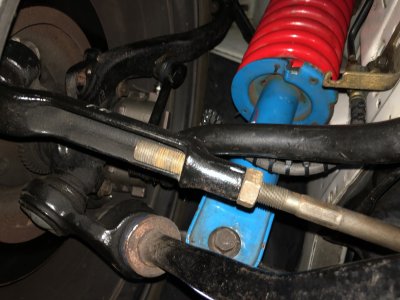
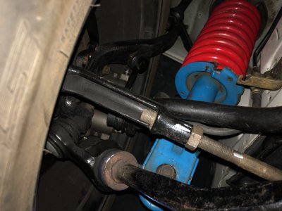
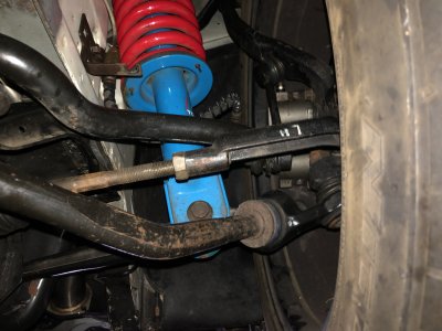
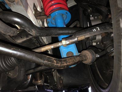
Here’s a two birds with one stone project, primarily dealing with the steering wheel centering issue I attempted to remedy after swapping back to a stock shaft with my mustang rack after the Kooks swap. Back in July I first tried adjusting the tie rods which ended up WAY on the edge of adjustment on the left side. Shortly after being uncomfortable with that I modified the end of the steering shaft which slightly re-clocked it for the better(you can see that work earlier in this thread), but it only made a little improvement in thread engagement between the left inner/outer tie rod, the underlying problem remained but I tried ignoring it since at least the wheel was centered now. The real problem I soon discovered was at full lock taking tight right turns the spindle wasn't even close to the stop, I'd literally need to make 3 point turns turning into parking spaces, which quite frankly is why I haven’t felt like driving it much this season.

So yesterday I decided to prod at it, nearly short of removing the rack to see if theres anything else causing me to chase my tail before proceeding with the plan I have had in mind, and suffice to say it all checks out. What still baffles me is know a few of you followed my lead with the Cobra rack with the triangle end and U joint but I don’t remember any issues like this mentioned using it with a stock shaft(I always had a custom relocated setup with this rack that worked great until this). But this is the circumstance with mine so I'm making it work, so is life as a hot rodder.

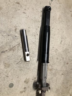
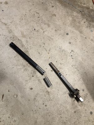
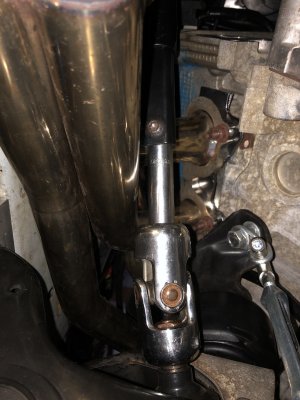
So here's the solution, 3/4 round shaft(it actually was the splined SS borgenson piece from my old setup) with the ends ground into DD OFFSET by the amount the steering wheel was off with the rack centered. All fixed! What's the second bird I killed you ask? Well @97 30th had header interference issues with the unisteer joint I’m also using and the stock coupler hardware, and his solution he showed in his excellent build thread was using an extended stub that moves the coupler section between primaries, having just the thinner 3/4" section pass next to the primary tube with room to spare. Mine didn’t really need it but it's peace of mind at least

Lastly but related is since I effectively moved the shaft back about 2" it took away most of its collapsibility. So what I did was cut 2" from the sleeve portion on the interior side as well as drill out the internal dimple that is supposed to stop the inner DD section of breakaway shaft in it.

IMG_7692.jpeg

IMG_7690.jpeg

IMG_7695.jpeg

Here’s the tie rods before/after with the wheel centered

Right side
IMG_7083.jpegIMG_7697.jpeg

Left side
IMG_7084.jpegIMG_7698.jpeg

IMG_7699.jpeg


Edited for clarity
 
Last edited:

Similar threads

Back
Top